Light emitting diode driving circuit for backlight having constant current control function

a technology of driving circuit and diode, which is applied in the field of backlight units, can solve the problems of low response rate of about 15 ms, low color reproducibility and inability to detect current, and low color reproducibility of light-weighted and small-sized lcd panels. achieve the effect of improving driving current detection

Active Publication Date: 2007-01-04
SAMSUNG ELECTRONICS CO LTD
View PDF5 Cites 65 Cited by
  • Summary
  • Abstract
  • Description
  • Claims
  • Application Information

AI Technical Summary

Benefits of technology

[0020] The present invention has been made to solve the foregoing problems of the prior art and it is therefore an object of the present invention to provide an LED driving circuit of a backlight unit in use for

Problems solved by technology

The CCFL has some drawbacks such as environmental contamination due to mercury gas contained therein, low response rate of about 15 ms, low color reproducibility and inaptness to a light-weighted and small-sized LCD panel.
However, when the switch SW is off, current is not

Method used


Image

  • Light emitting diode driving circuit for backlight having constant current control function
  • Light emitting diode driving circuit for backlight having constant current control function
  • Light emitting diode driving circuit for backlight having constant current control function

Examples


Embodiment Construction

[0035] Preferred embodiments of the present invention will now be described more fully hereinafter with reference to the accompanying drawings, in which the similar reference signs are used to designate the similar components throughout.

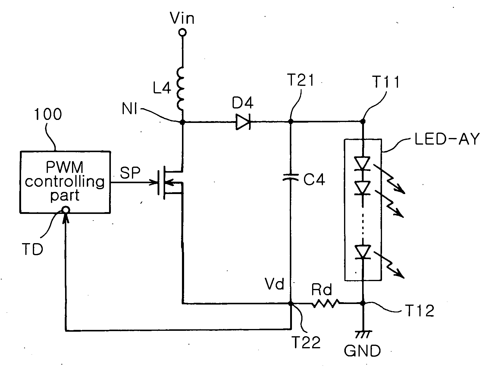
[0036]FIG. 4 shows an LED driving circuit of a backlight unit according to the invention.

[0037] Referring to FIG. 4, the LED driving circuit of a backlight unit of the invention is a circuit for driving an LED array LED-AY including a plurality of LEDs connected in series, and includes a switch SW4, a rectifying diode D4, a smoothing capacitor C4, a voltage detecting resistor Rd and a PWM controlling part 100.

[0038] The switch SW4 is connected between an input of direct voltage Vin and a ground GND. The switch SW4 switches the direct voltage Vin according to a switching pulse SP. In this embodiment of the invention, the switch SW4 is constructed of an MOS transistor having a drain connected to the input of the direct voltage Vin, a source connecte...


PUM


Abstract

An LED driving circuit of a backlight unit includes a switch connected between an input of direct voltage and a ground to switch the direct voltage according to a switching pulse; a rectifying diode connected between a connecting node and one terminal of the LED array to rectify driving voltage supplied according to switching operation of the switch; a smoothing capacitor having one terminal connected to a cathode of the rectifying diode and the other terminal connected to a ground; a voltage detecting resistor connected between the other terminal of the LED array connected to the ground and the other end of the smoothing capacitor to detect voltage from the current flowing to the ground; and a PWM controlling part for controlling on/off status of the switching according to the switching pulse, wherein the switching pulse has a duty ratio determined according to a preset internal reference voltage and the voltage detected by the voltage detecting resistor. The driving current of can be controlled at a constant current and thus be stabilized.

Description

CLAIM OF PRIORITY [0001] This application claims the benefit of Korean Patent Application No. 2005-58476 filed on Jun. 30, 2005, in the Korean Intellectual Property Office, the disclosure of which is incorporated herein by reference. BACKGROUND OF THE INVENTION [0002] 1. Field of the Invention [0003] The present invention relates to a backlight unit in use for an LCD panel, and more particularly, to an LED driving circuit of a backlight unit which has an improvement in driving current detection, by which driving current of a light source of the backlight unit such as LEDs can be controlled at a constant current and thus be stabilized. [0004] 2. Description of the Related Art [0005] In general, a backlight source for a Liquid Crystal Display (LCD) panel such as an LCD TV and LCD monitor uses a light-emitting device such as a Cold Cathode Fluorescent Lamp (CCFL) and a Light Emitting Diode (LED). [0006] The CCFL has some drawbacks such as environmental contamination due to mercury gas ...

Claims


Application Information

Patent Timeline
IPC IPC(8): H05B39/00G02F1/133H01L33/00H05B37/02
CPCH05B33/0815Y02B20/347H05B33/0854H05B45/10Y02B20/30H05B45/38G02F1/133
Inventor KIM, DO HUN
Owner SAMSUNG ELECTRONICS CO LTD
Why Eureka
Try Eureka