

Capacitor mounting type inverter unit
a technology of inverter unit and capacitor, which is applied in the direction of electric variable regulation, process and machine control, instruments, etc., can solve the problems of increasing electrical contact resistance, volume, weight, cost, and assembling steps, and reducing the number of parts, volume, weight, and cost.
- Summary
- Abstract
- Description
- Claims
- Application Information
AI Technical Summary
Benefits of technology
Problems solved by technology
Method used
Image

Examples
Embodiment Construction
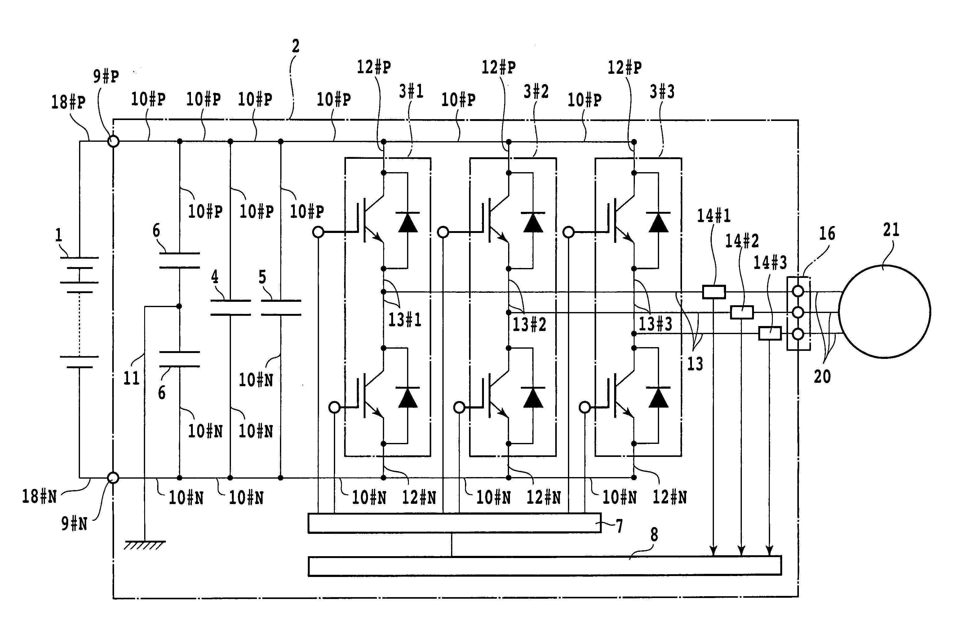
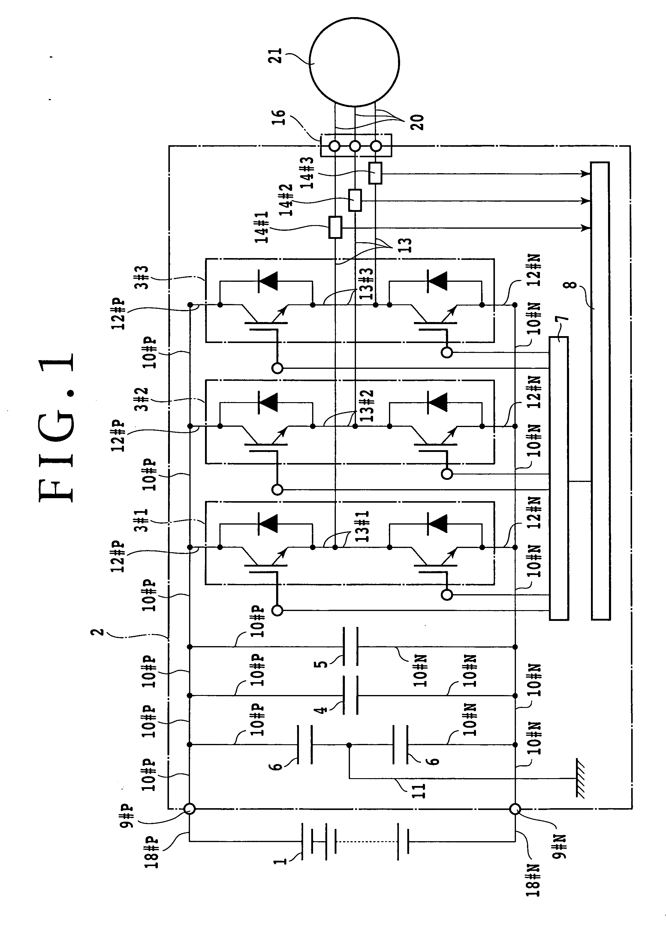
[0051]FIG. 1 is a circuit diagram showing a capacitor mounting type inverter unit 2 adapted to be provided in an electric vehicle or a hybrid vehicle, for example. As shown in FIG. 1, input lines 18#P and 18#N are connected to the positive and negative electrodes of a battery 1, respectively. The input lines 18#P and 18#N are connected to the inverter unit 2. The inverter unit 2 includes a plurality of phases (e.g., three phases) of SW modules 3#i (i=1, 2, 3), a plurality of smoothing capacitors 4 connected in parallel to each other, a noise absorbing capacitor (C snubber) 5 connected in parallel to the smoothing capacitors 4, a plurality of (e.g., two) noise absorbing capacitors 6 cascaded each other and connected in parallel to the smoothing capacitors 4, a SW module control board 7, a control ECU 8, input terminal bases 9#P and 9#N, input bus bars 10#P and 10#N, a ground line 11, SW module input bus bars 12#P and 12#N, SW module output bus bars 13#i (i=1, 2, 3), current sensors 1...
PUM
 Abstract
Description
Claims
Application Information