
Optical disk, optical disk access device and access method

a technology of optical disk and access device, which is applied in the field of optical disk and optical disk access device and access method, can solve the problems of increasing production cost, increasing part cost, and reducing the data density of the recording medium, so as to reduce the overhead of the control information portion, the effect of rapid access and reduced overhead

Inactive Publication Date: 2007-01-04
FUJITSU LTD
View PDF5 Cites 2 Cited by
  • Summary
  • Abstract
  • Description
  • Claims
  • Application Information

AI Technical Summary

Benefits of technology

The present invention provides a recording medium, such as an optical disk, that can securely and quickly access data while reducing the overhead of control information. This is achieved by gathering information units with data portions and control information portions, and using group data identification information to identify each information unit. The control information portion contains recognition information that can uniquely identify each information unit group. The recording medium can achieve higher data density without increasing manufacturing costs or part costs. The access device and access method of the invention allow for rapid positional error detection and access to recording media with small overhead.

Problems solved by technology

Further, to achieve miniaturization in the emboss pit pattern of the controlling bit patterns 115, 215 in the control information portions 110, 210, the processing accuracy in manufacturing process needs to be improved thereby inducing an increase in production cost.
Further, if the size of the emboss pit pattern in the controlling bit pattern 115, 215 is miniaturized, it is necessary to use short wavelength laser such as blue laser as the wavelength of a pick-up laser beam, inducing an increase in part cost.
However, in this case, if a beam spot of laser or the like suffers from a positional error generated from a normal access position, detection of normal access position is disabled or it takes an extremely long time for the detection, so that there is a fear that an access to a mistaken position may be made, which is a problem to be solved.

Method used


Image

  • Optical disk, optical disk access device and access method
  • Optical disk, optical disk access device and access method
  • Optical disk, optical disk access device and access method

Examples


Embodiment Construction

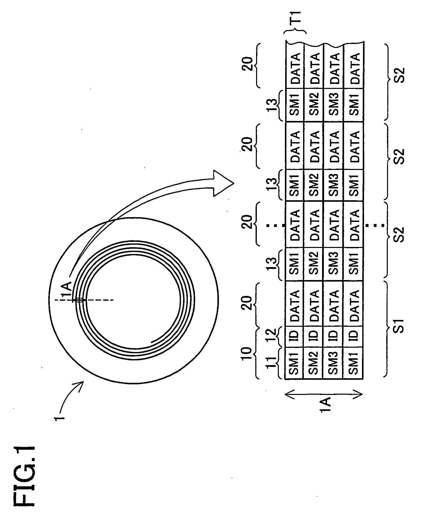
[0042] Hereinafter, the embodiment of the recording medium represented by the optical disk, access device and access method of the present invention will be described in detail with reference to FIGS. 1-8. FIG. 1 shows the optical disk 1 of this embodiment. Like the high-density optical disk 200 based on the conventional art, the land groove recording type is adopted. The data portion 20 is constructed in both the land and groove so as to achieve high density. In the optical disk 1, as shown in the enlarged view of the 4-track 1A, each track T1 includes two sectors, namely, a sector S1 containing the sector mark portion 11 and the ID portion 12 in its control information portion 10 and a sector S2 containing only sector mark portion 13. That is, the control information portion in the sector S2 is just the sector mark portion 13. The sector S1 is a first sector of the track T1 followed by the sector S2. Only the first sector S1 is provided with the ID portion 12. Further, the same se...


PUM

PropertyMeasurementUnit
data lengthaaaaaaaaaa
temperature distributionaaaaaaaaaa
densityaaaaaaaaaa

Abstract

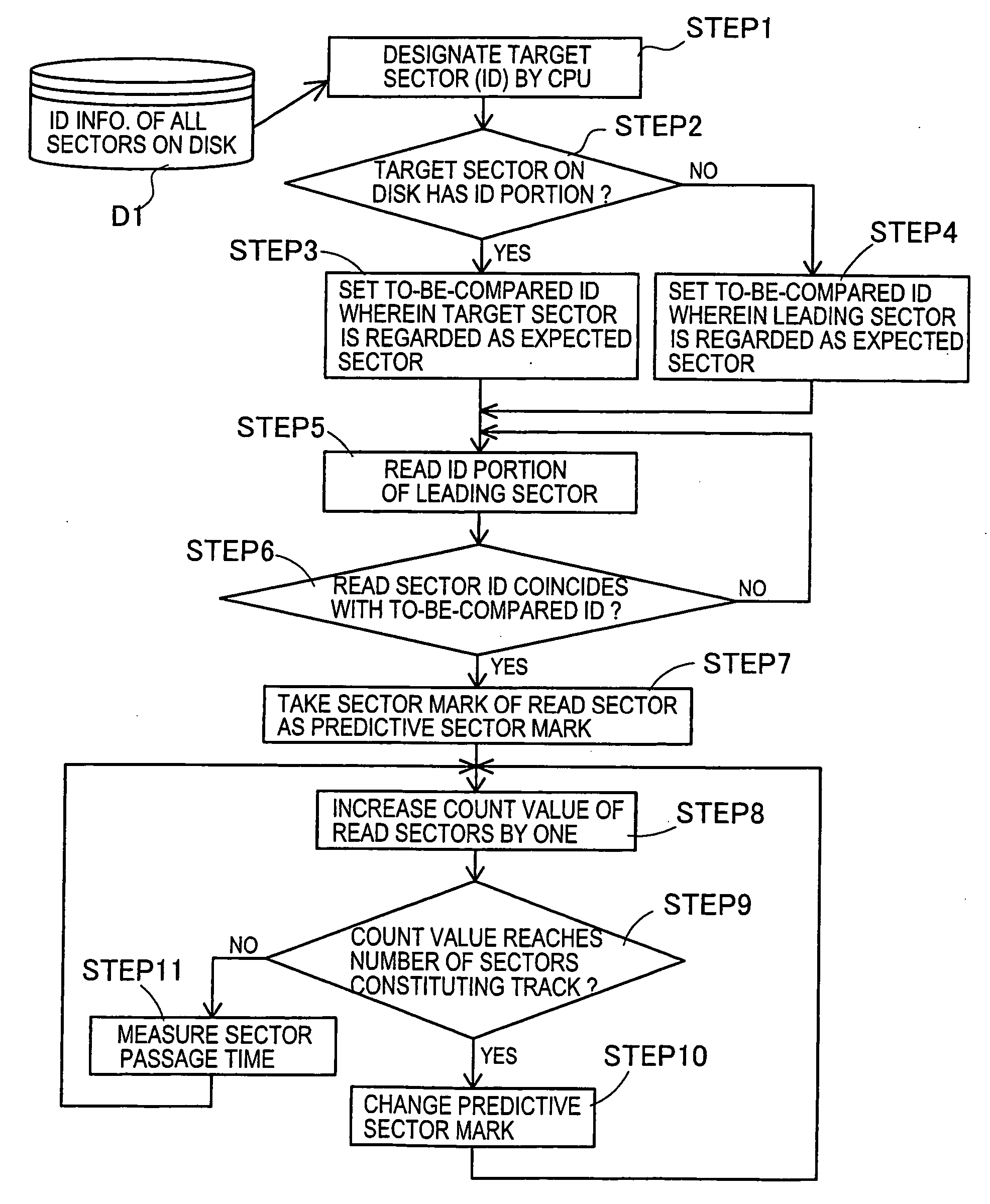
An optical disk having an increased data storage capacity and accessible randomly, the positional shift of which can be quickly detected. An optical disk access device and access method are also disclosed. The optical disk (1) has a track (T1) constructed of two kinds of the first sector (S1) having an ID portion (12) and succeeding sectors (S2) having only a sector mark portion (13), and sector marks of the tracks are different from one another. The data area is increased by compressing the ID portion, and the different marks of the tracks enable quick detection of access positional shift.

Description

CROSS-REFERENCE TO RELATED APPLICATIONS [0001] This application is a divisional of application Ser. No. 10 / 819,263, filed Apr. 7, 2004. This application is a continuation application based upon and claims the benefit of the prior PCT International Patent Application No. PCT / JP01 / 09306 filed on Oct. 23, 2001, the entire contents of which are incorporated herein by reference.BACKGROUND OF THE INVENTION [0002] 1. Field of the Invention [0003] The present invention relates to a recording medium represented by an optical disk optically rewritable, an access device and an access method. More particularly, the present invention relates to an optical disk which enables a quick random access operation if the disk is formed into a large capacity, an access device and an access method. [0004] 2. Description of Related Art [0005] Conventionally, there is a recording medium provided with data identification information for each information unit of a predetermined data length in order to carry ou...

Claims


Application Information

Patent Timeline
Patent Type & Authority Applications(United States)
IPC IPC(8): G11B21/08G06F12/00G11B7/00G11B7/007G11B7/085G11B20/12
CPCG11B7/00718G11B2220/2537G11B7/08505G11B11/10563G11B11/10565G11B20/1217G11B27/24G11B2020/1232G11B2020/1265G11B2020/1274G11B2020/1287G11B2020/1292G11B2020/1295G11B2220/216G11B2220/2525G11B7/00745G11B7/007
Inventor HORIBE, KOJI
Owner FUJITSU LTD
Learn More