
Low loss optical fiber designs and methods for their manufacture

a technology of optical fiber and design method, applied in the field of optical fiber design, can solve the problems of optical fiber loss characteristics produced using these methods, and achieve the effects of reducing the level of dopant related excess scattering loss, high productivity, and different loss characteristics

Inactive Publication Date: 2007-01-04
OFS FITEL LLC
View PDF8 Cites 71 Cited by
  • Summary
  • Abstract
  • Description
  • Claims
  • Application Information

AI Technical Summary

Benefits of technology

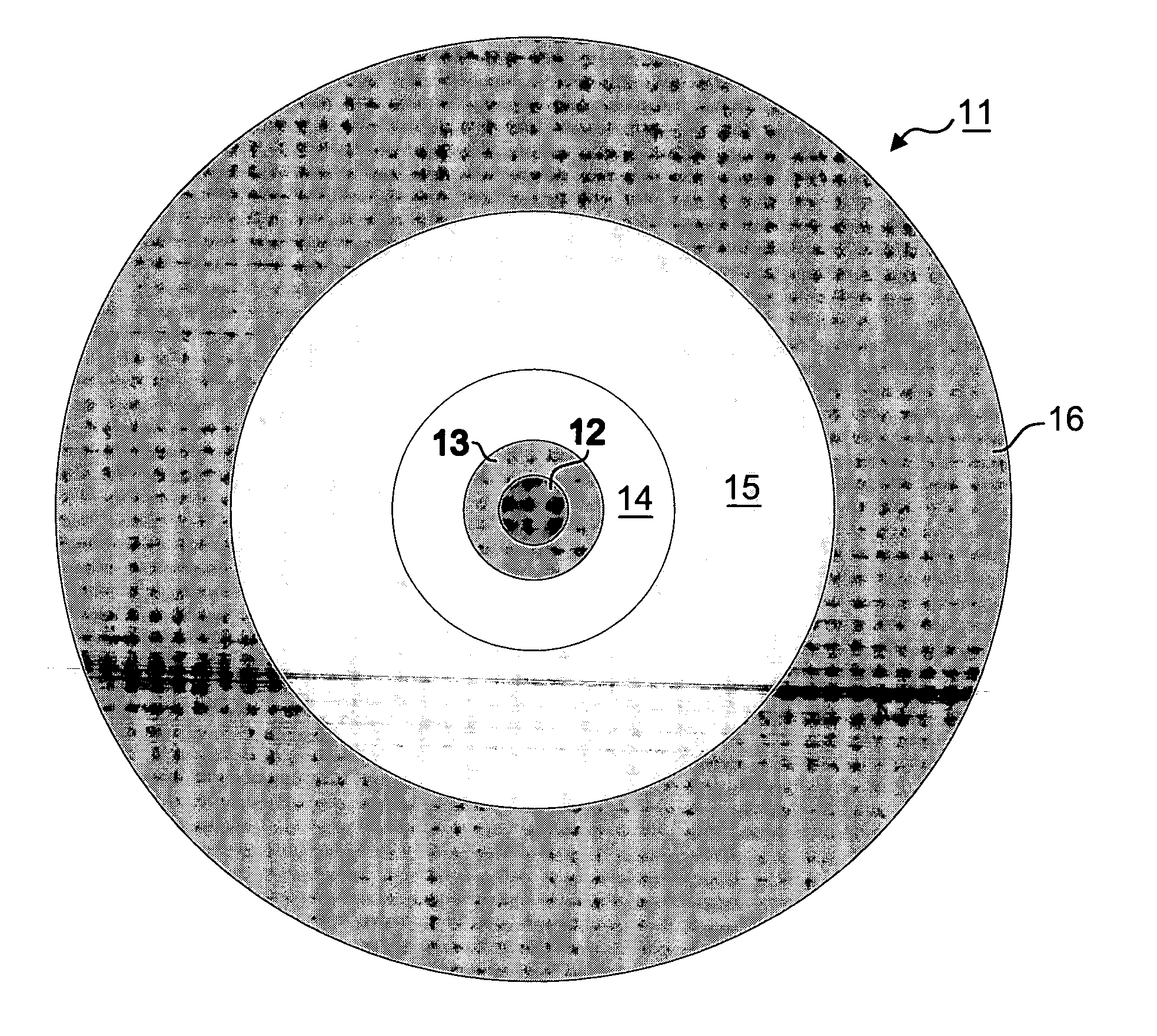
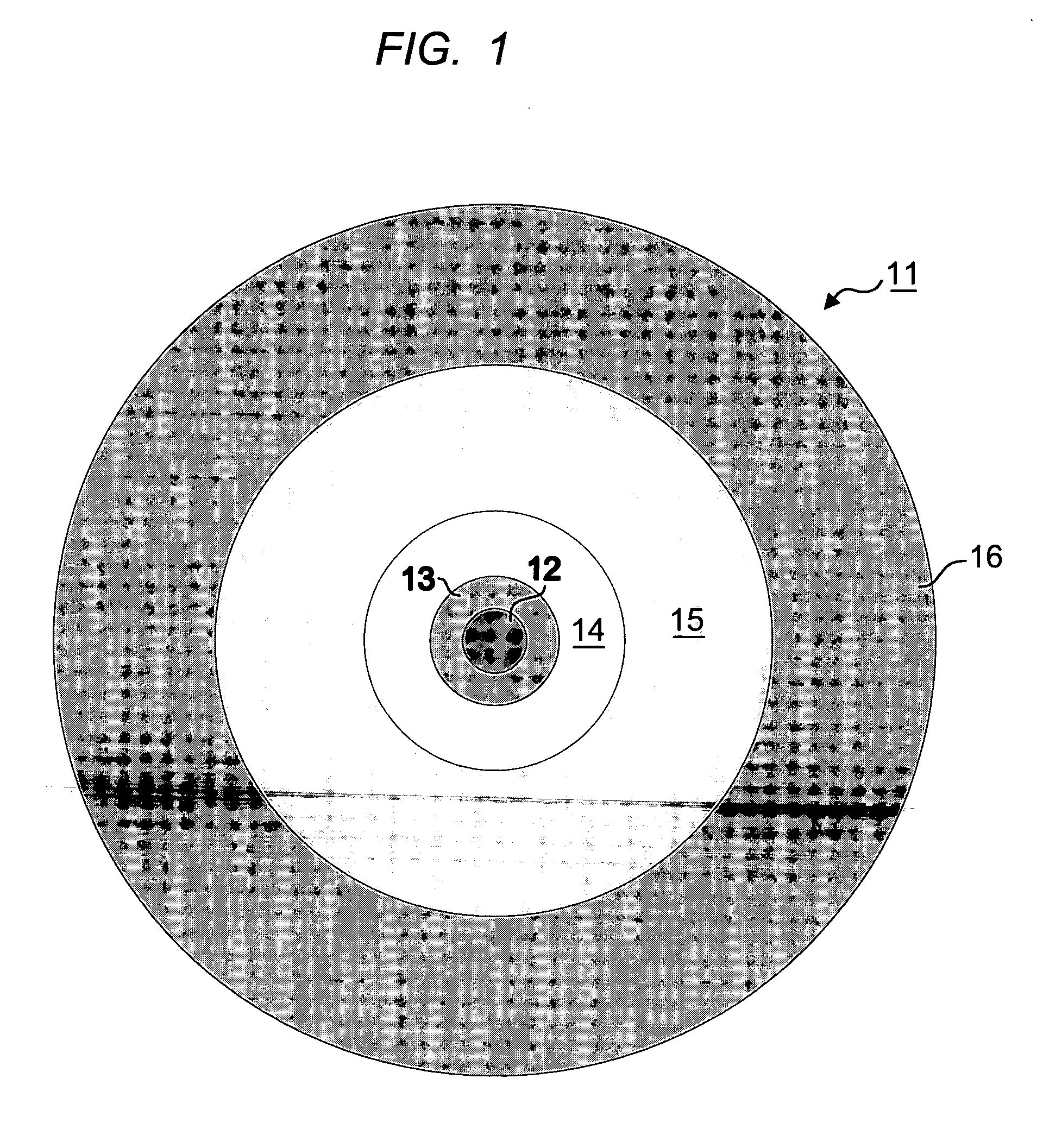
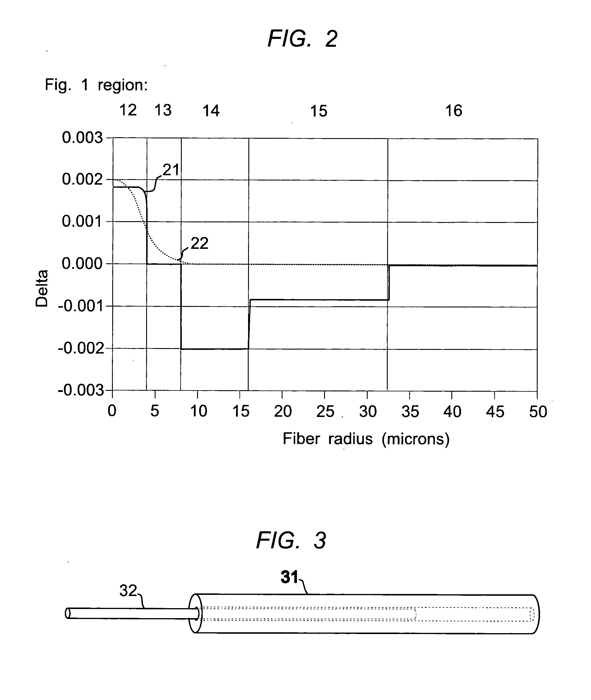
[0011] We have designed a set of optical fiber index profiles that reduce the level of dopant related excess scattering loss, and have developed a hybrid method for producing optical fibers using a combination of MCVD and VAD that significantly advance the prior art in terms of loss and high productivity. The hybrid method combines the desirable features of each processing technique. We have also noted the loss characteristics of optical fiber produced using these methods. Recognizing that the loss characteristics are different, we have combined the MCVD and VAD techniques to optimize the composite loss characteristic. The profile design can be optimized to distribute the optical power so as to reduce Rayleigh scattering, while achieving nearly zero water peak 1385 nm loss performance and maintaining good macrobending performance. In the preferred embodiment of the invention a VAD method is used to produce a core rod, with an up-doped inner core and a less heavily doped, or undoped, outer core. An MCVD method is used to produce a cladding with one or more depressed index regions. Using this basic preform fabrication approach, we adapt the profile and the optical power envelope such that essentially all of the optical power is contained in either the VAD material and the MCVD material, and most of the power envelope is contained in the VAD material, with for example typically 60% of the power contained in the VAD inner core, which has Ge-doping levels that are typically less than 60% of that found in standard single mode fiber cores, and with for example 20-40% of the power contained in the undoped or lightly doped VAD outer core.

Problems solved by technology

We have also noted the loss characteristics of optical fiber produced using these methods.

Method used


Image

  • Low loss optical fiber designs and methods for their manufacture
  • Low loss optical fiber designs and methods for their manufacture
  • Low loss optical fiber designs and methods for their manufacture

Examples


Embodiment Construction

[0020] Low loss fibers with low or zero water peaks are effectively produced by the VAD or OVD methods in large economical preform sizes (greater than 90 mm OD). The lowest 1385 nm losses (specified less than 0.31 dB / km and typically 0.275 dB / km) are most consistently achieved with core rods produced by the VAD method, in preform sizes as large as 150 mm. The MCVD method is typically used to produce smaller preforms (60 to 90 mm) with somewhat relaxed water peak specifications compared to VAD. This commercial practice results from the fact that core material deposited by VAD or OVD is usually inherently more dry ([OH]<1 ppb) due to the dehydration of the soot prior to sintering. A second causative reason is that it is possible to make large bodies with large D / d ratios with VAD or OVD; this means that the first overcladding interface can be far away from the core (i.e. low optical power) in a large core body (much greater than 90 mm). The MCVD process normally produces to lower D / d ...


PUM

PropertyMeasurementUnit
depthaaaaaaaaaa
depthaaaaaaaaaa
radiusaaaaaaaaaa

Abstract

The specification describes an improved optical fiber produced by a hybrid VAD / MCVD process. The core of the fiber is produced using VAD and the inner cladding layer has a depressed index and is produced using MCVD. In preferred embodiments, the optical power envelope is essentially entirely contained in VAD produced core material and the MCVD produced depressed index cladding material. Optical loss is minimized by confining most of the optical power to the VAD core where OH presence is low, as well as by maximizing the optical power in the un-doped silica region. The MCVD substrate tube material is essentially devoid of optical power.

Description

FIELD OF THE INVENTION [0001] This invention relates to a family of designs for optical fibers and methods for producing optical fibers employing those designs having improved optical transmission characteristics. More specifically it relates to a hybrid production method wherein optical fiber preforms are fabricated using a combination of MCVD and VAD techniques, wherein the VAD-MCVD interface is inside the waveguide-forming region of the refractive index profile design. BACKGROUND OF THE INVENTION [0002] A wide variety of methods have been proposed and explored for producing optical fibers. As optical fiber technology has matured, three main production methods, MCVD, VAD, and OVD have emerged. All involve the deposition of glass particulates (frequently referred to as “soot”) on a starting substrate, then consolidating the particulates into a solid glass body. The techniques involve producing the particulates using an in situ vapor phase reaction. The vapor phase reaction is induc...

Claims


Application Information

Patent Timeline
Patent Type & Authority Applications(United States)
IPC IPC(8): G02B6/02C03B37/018C03B37/01C03C25/00
CPCC03B37/01211C03B37/01228C03B37/014C03B37/018G02B6/03683C03B2201/075C03B2201/12C03B2201/31C03B2203/22C03B2201/04
Inventor GIBSON, LANCEPECKHAM, DAVIDLINGLE, ROBERT JR.
Owner OFS FITEL LLC
Learn More