Optical waveguide feedthrough assembly

Inactive Publication Date: 2007-01-04
WEATHERFORD TECH HLDG LLC
View PDF35 Cites 29 Cited by
  • Summary
  • Abstract
  • Description
  • Claims
  • Application Information

AI Technical Summary

Benefits of technology

[0014] Embodiments of the present invention provide an optical waveguide feedthrough assembly, and a method of making such an assembly, which overcomes one or more of

Problems solved by technology

In addition, one or both sides of the feedthrough member may be subjected to relatively high temperatures and other harsh environmental conditions, such as corrosive or volatile gas, fluids and other materials.
There are several problems associated with constructing such an optical fiber feedthrough.
One of these problems is the susceptibility of the glass fiber to damage and breakage.
This is due to the flexibility of the small size fiber, the brittle nature of the glass material, and the typical presence of a significant stress concentration at the point where the fiber enters and exits the feedthrough.
Attempts to use a sealing glass, such as that used with electrical feedthroughs, have had problems of this nature due to the high stress concentration at the fiber-to-sealing glass interface.
Another problem with sealing an optical fiber, as opposed to sealing a conductive metal “pin” in an electrical feedthroug

Method used


Image

  • Optical waveguide feedthrough assembly
  • Optical waveguide feedthrough assembly
  • Optical waveguide feedthrough assembly

Examples


Embodiment Construction

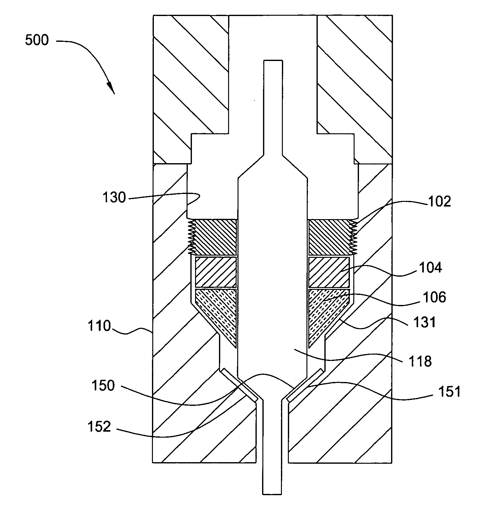
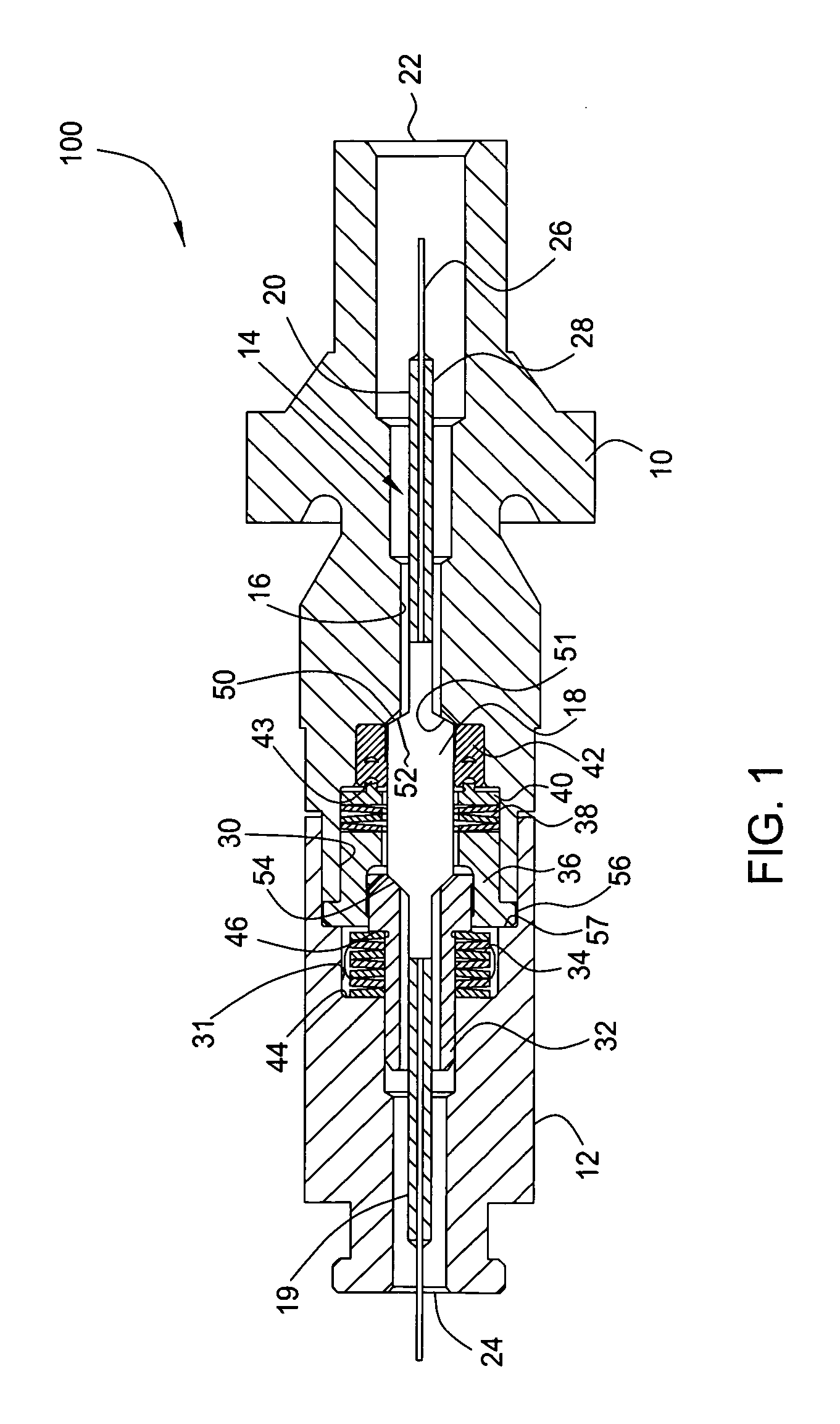
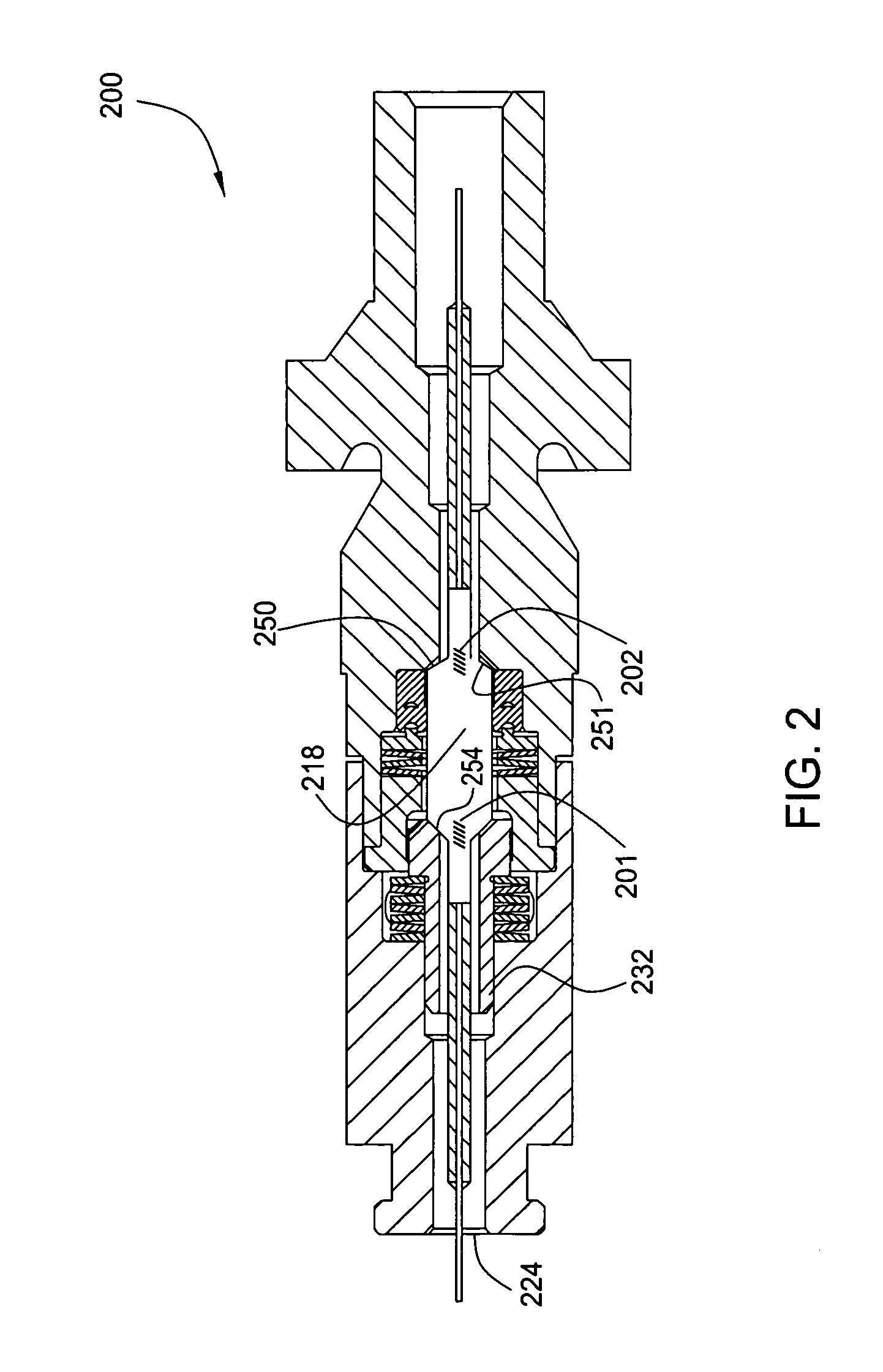
[0027] Epoxy-free optical fiber feedthrough assemblies applicable for use in high temperature, high pressure environments are provided. In one embodiment, a feedthrough assembly includes a glass plug disposed in a recess of a feedthrough housing. The glass plug is preferably a large-diameter, cane-based, waveguide adapted to seal the recess in the housing and provide optical communication through the housing. All embodiments described herein provide for sealing with respect to the housing at or around the glass plug of an optical waveguide element passing through the housing.

[0028] As used herein, “optical fiber,”“glass plug” and the more general term “optical waveguide” refer to any of a number of different devices that are currently known or later become known for transmitting optical signals along a desired pathway. For example, each of these terms can refer to single mode, multi-mode, birefringent, polarization maintaining, polarizing, multi-core or multi-cladding optical waveg...


PUM


Abstract

An optical waveguide feedthrough assembly passes at least one optical waveguide through a bulk head, a sensor wall, or other feedthrough member. The optical waveguide feedthrough assembly comprises a cane-based optical waveguide that forms a glass plug sealingly disposed in a feedthrough housing. For some embodiments, the optical waveguide includes a tapered surface biased against a seal seat formed in the housing. The feedthrough assembly can include an annular gold gasket member disposed between the tapered surface and the seal seat. The feedthrough assembly can further include a backup seal. The backup seal comprises an elastomeric annular member disposed between the glass plug and the housing. The backup seal may be energized by a fluid pressure in the housing. The feedthrough assembly is operable in high temperature and high pressure environments.

Description

CROSS REFERENCE TO RELATED APPLICATIONS [0001] This application is related to application Ser. No. ______, (Attorney Docket Number WEAT / 0677) filed herewith, entitled “Pressure Transducer with Optical Waveguide Feedthrough Assembly,” which is herein incorporated by reference in its entirety. BACKGROUND OF THE INVENTION [0002] 1. Field of the Invention [0003] The present invention relates to feedthroughs for optical waveguides, and more particularly, to hermetically sealed feedthroughs suitable for use in high pressure, high temperature, and / or other harsh environments. [0004] 2. Description of the Related Art [0005] In many industries and applications, there is a need to have small diameter wires or optical waveguides penetrate a wall, bulkhead, or other feedthrough member wherein a relatively high fluid or gas differential pressure exists across the feedthrough member. In addition, one or both sides of the feedthrough member may be subjected to relatively high temperatures and othe...

Claims


Application Information

Patent Timeline
IPC IPC(8): G02B6/00
CPCE21B47/123G01L11/025G02B6/24G02B6/4428G02B6/4248E21B47/135
Inventor DUNPHY, JAMES R.SGAMBELLURI, JOHN J.GRUNBECK, JOHNTALMADGE, GEORGEROBINSON, ROBERT F.SULLIVAN, JAMES M.ROBBINS, JOSEPH F.
Owner WEATHERFORD TECH HLDG LLC
Why Eureka
Try Eureka