
Method and apparatus for segregation testing of particulate solids

a technology of particulate solids and segregation, which is applied in the direction of instruments, measurement devices, scientific instruments, etc., can solve the problems of entraining particles in the gas stream, reducing the likelihood of gas channeling, so as to reduce cost and material waste, reduce errors and material losses, and less test material

Inactive Publication Date: 2007-01-11
JENIKE & JOHANSON
View PDF1 Cites 3 Cited by
  • Summary
  • Abstract
  • Description
  • Claims
  • Application Information

AI Technical Summary

Benefits of technology

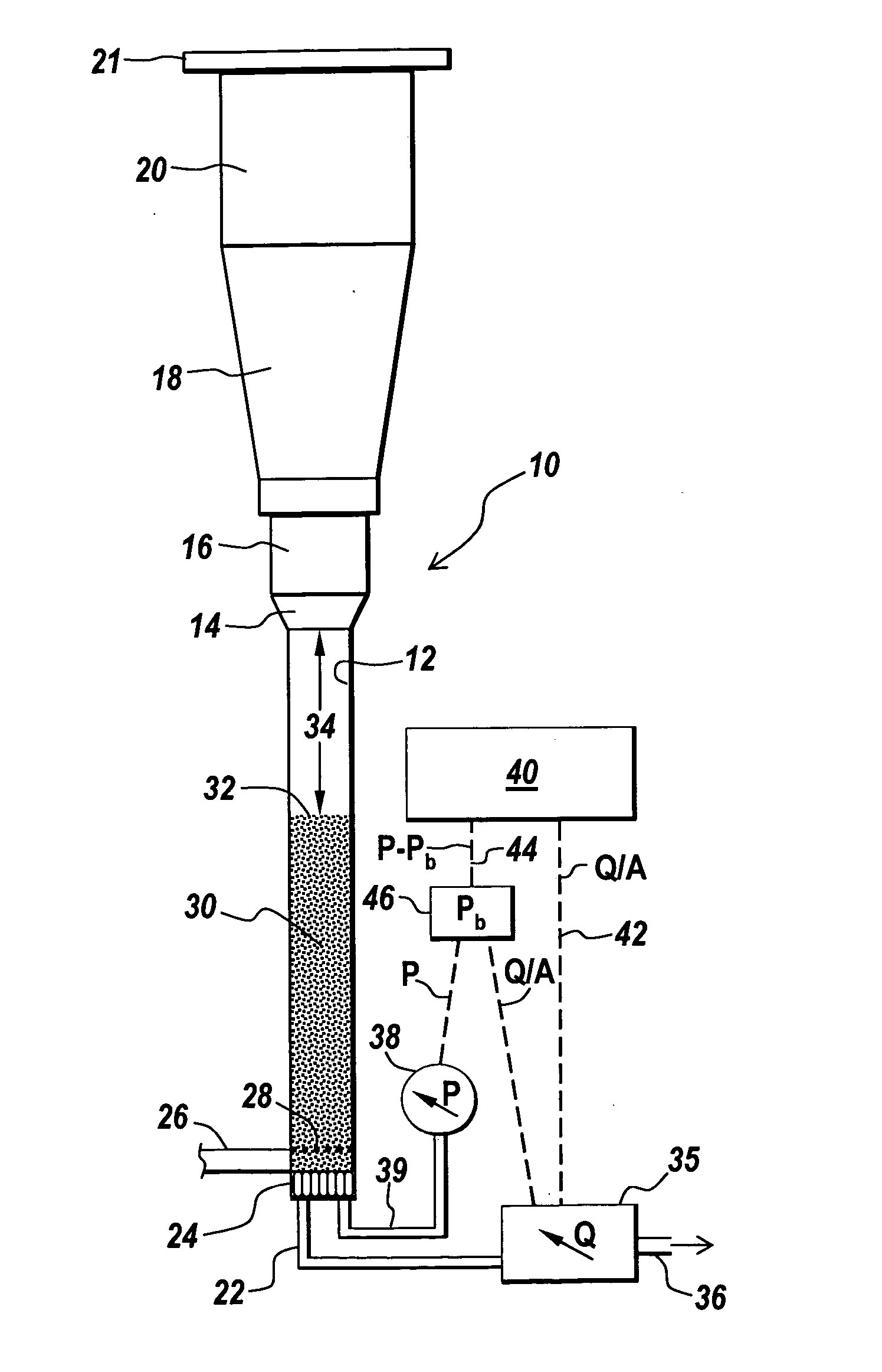
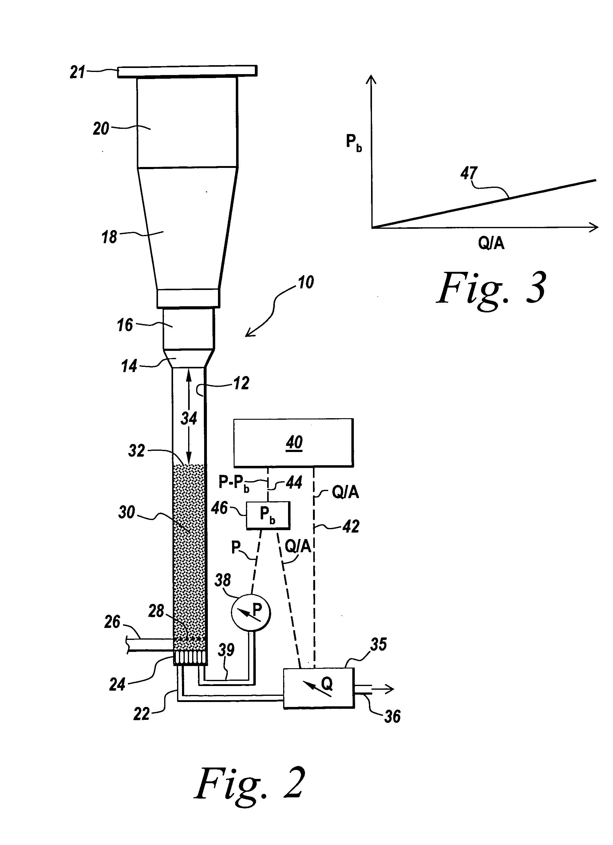
[0013] With the object of overcoming the above and other drawbacks, the features of this invention include a flow rate cycling or ramp-up method of controlling the gas flow rate for the achievement of fluidization in the test chamber. This method permits the fluidization of materials that do not fluidize easily, and reduces the likelihood of channeling of the gas, cohesive effects, and entraining of particles in the gas stream.
[0016] An indicating function is produced and may be plotted to show values of the net pressure drop as a function of the gas flow rate. Observation of this function permits less subjective evaluation of the state of fluidization and subsequent control of the test, as hereinafter more particularly described.
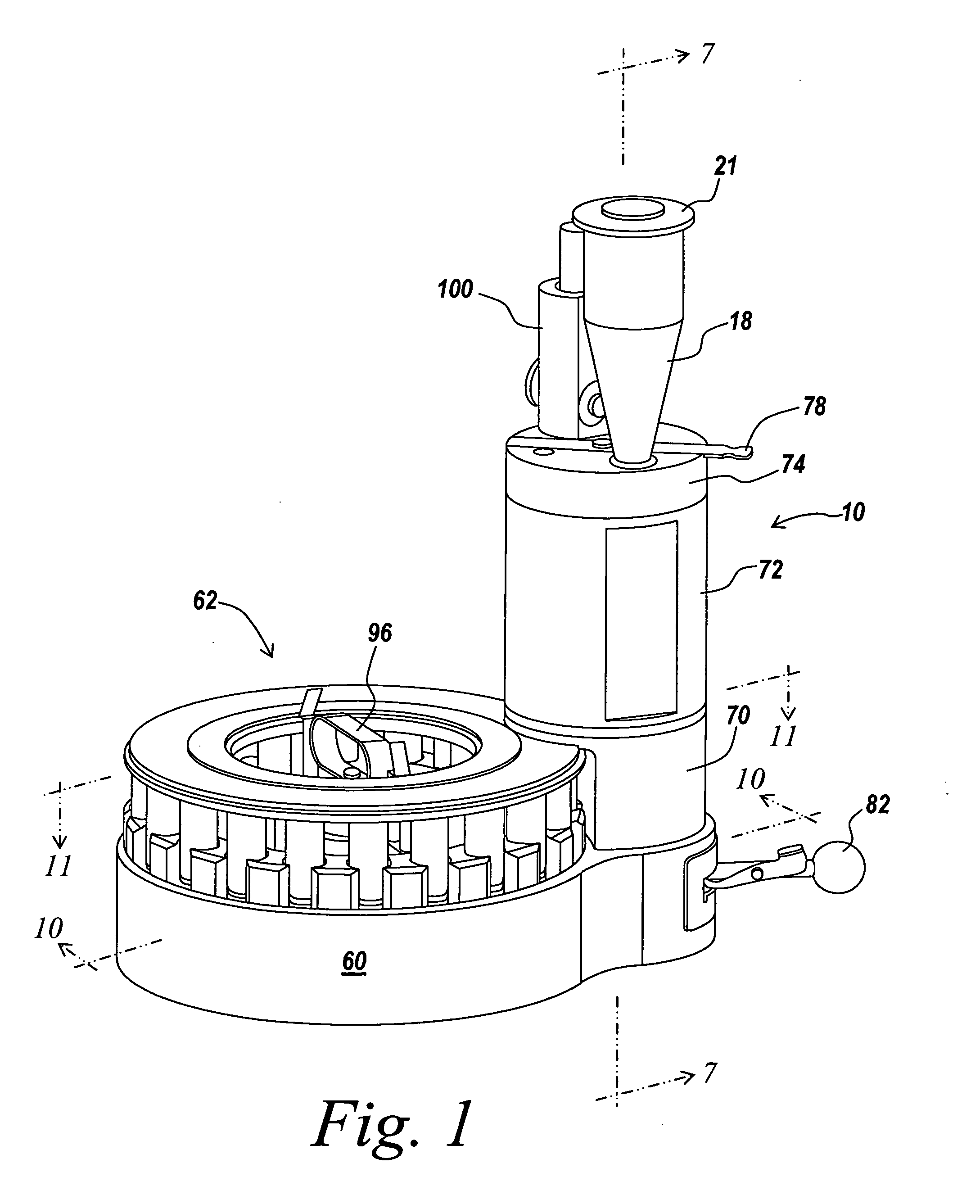
[0017] A feature of the invention is an improved method of extracting samples from the test chamber. The samples at a plurality of vertical levels are sequentially removed from the bottom of the chamber. The samples are of small size as compared, for example, to those obtained with the apparatus of Pat. No. 6,487,921, and are preferably equal in volume to that required for assays or other methods of analysis. This eliminates the need to sub-sample or subdivide the sample by riffling, both of which take additional time and can result in errors and material losses.
[0018] Another feature of the invention is that it enables the use of a test chamber of smaller size than the chamber used in the existing apparatus, requiring as little as 19 ml per test, for example, while being effective even for more cohesive materials. This reduces cost and material waste, and may allow testing in some cases where larger samples cannot be provided.
[0019] As a consequence of the foregoing and other features hereinafter described, the invention uses less test material, provides increased sensitivity to and resolution of segregation that has occurred, is more likely to reach full fluidization of the test material, reduces the subjectivity of the observations and control of test conditions, and produces samples of a size that can be used directly in common assay methods.

Problems solved by technology

This method permits the fluidization of materials that do not fluidize easily, and reduces the likelihood of channeling of the gas, cohesive effects, and entraining of particles in the gas stream.

Method used


Image

  • Method and apparatus for segregation testing of particulate solids
  • Method and apparatus for segregation testing of particulate solids
  • Method and apparatus for segregation testing of particulate solids

Examples


example

[0060] A test chamber 16 mm in diameter was filled with a particulate material to a level of 95 mm. A five micron sintered metal diffuser disk 24 was fitted at the base of the chamber. A “target flow rate” was estimated, by prior test work and theoretical calculations, to be slightly above the lowest level sufficient to sustain fluidization. This target rate was divided by 7, the estimated number of cycles to complete the test, thus determining the increment of velocity Q / A to be added to each successive cycle.

[0061] Upon completion of the test, sixteen 1.2 mil samples, each of which was located at a distinct level or position during the test, were successively recovered from the chamber. Even numbered samples were assayed for percent of intent and odd numbered samples were measured to determine particle size distribution. The results are illustrated in FIG. 6, and show that assay and particle size variations are pronounced, indicating possible segregation problems with this materi...


PUM

PropertyMeasurementUnit
diameteraaaaaaaaaa
pressureaaaaaaaaaa
gas flow rateaaaaaaaaaa

Abstract

A bed of particulate solids is fluidized in a test chamber to yield multiple test samples for subsequent evaluation of segregation effects. A controlled stream of gas enters the chamber in a series of flow rate cycles each progressively increasing to a maximum rate of gas flow and then decreasing, the maximum rate increasing for successive cycles. An indicating function is formed from measurements of corresponding rates of gas flow and pressure across the bed. Upon termination of the fluidization, multiple samples are sequentially extracted from a single space at the bottom of the test chamber.

Description

BACKGROUND OF THE INVENTION [0001] This invention relates to a method and apparatus useful for testing powders and other particulate bulk solids with the object of evaluating their segregation tendencies when fluidized under industrial conditions. [0002] To facilitate the industrial processing of powders and other particulate solids it is common practice to blow air or other gas into the body of the material. At a sufficient gas flow rate this results in fluidization, a state in which the solids exhibit fluid-like properties. Fluidization may also occur unintentionally, for example during transfer of powder from a blender to a bin, when air flow through the material may fluidize or partially fluidize the material. [0003] However, fluidization is the driving force for a segregation mechanism that alters the uniformity of the properties of the solids in different parts of the body, notably the particle size distribution, but also other properties including for example particle shape, ...

Claims


Application Information

Patent Timeline
Patent Type & Authority Applications(United States)
IPC IPC(8): G01N15/00
CPCG01N15/04
Inventor BRONE, DEAN LANCECLEMENT, SCOTT A.HANCOCK, BRUNO CASPARHEDDEN, DAVID BRUCEMCCALL, MICHAEL A.PRESCOTT, JAMES K.TROXEL, THOMAS G.
Owner JENIKE & JOHANSON
Learn More