Intake airvolume controller of internal combustion engine

a technology of intake air and amount control, which is applied in the direction of machines/engines, process and machine control, output power, etc., can solve the problem of inability to correct the variation in the intake air amount between the cylinders, and achieve the effect of reducing power consumption and operation, reducing the load region, and opening and closing the intake valv

Inactive Publication Date: 2007-01-11
HONDA MOTOR CO LTD
View PDF5 Cites 12 Cited by
  • Summary
  • Abstract
  • Description
  • Claims
  • Application Information

AI Technical Summary

Benefits of technology

[0008] With the configuration of the intake air amount control system for an internal combustion, a variation parameter indicative of variation in intake air amount between a plurality of cylinders is calculated based on a model formed by modeling an intake system of the engine including an intake passage, according to a detected intake air amount parameter, on a cylinder-by-cylinder basis, and according to the variation parameter, a correction amount for correcting the amounts of intake air drawn into the cylinders is calculated on a cylinder-by-cylinder basis. According to the correction amount, a variable intake air amount device is controlled. As described above, since the variation parameter indicative of variation in intake air amount between the cylinders is calculated based on the model formed by modeling the intake system of the engine, by properly configuring the model, the variation parameter can be calculates such that it properly represents the variation in intake air amount between the cylinders. Further, the correction amount for correcting the amounts of intake air for the cylinders is calculated according to the thus calculated variation parameter, it is possible to properly correct and accommodate the variation in intake air amount between the cylinders. This makes it possible to prevent torque variation and rotational variation in a normal operation load region including a high load region, and ensure stable combustion. As a result, it is possible to improve drivability and exhaust emission characteristics.
[0010] With the configuration of this preferred embodiment, in the variation parameter-calculating means, the simulation value-generating means generates a plurality of simulation values; the estimation means estimates an estimated value of the intake air amount parameter based on a model defining a relationship between the estimated value and a plurality of simulation values simulating respective behaviors of the amounts of intake air drawn into the cylinders; and the identification means identifies a variation parameter based on the intake air amount parameter and the generated simulation values such that the estimated value of the intake air amount parameter becomes equal to the detected intake air amount parameter. As described above, since the variation parameter as a model parameter is identified such that the estimated value of the intake air amount parameter becomes equal to the detected intake air amount parameter, the variation parameter can be identified as a value in which the actual behaviors of the amounts of intake air drawn into the cylinders, i.e. variation in intake air amount between the cylinders is reflected. Therefore, since the correction amount for the intake air amount is calculated according to the variation parameter thus identified, the variation in the intake air amount between the cylinders can be properly and accurately corrected. Further, by using an onboard identifier as identification means, for example, it is possible to calculate the correction amount for the intake air amount based on the variation parameter identified in real time. As a consequence, as distinct from the prior art, even when the dynamic characteristics of the intake system as the controlled object have changed due to response variation or aging of the intake air amount parameter-detecting means, it is possible to correct and accommodate the variation in intake air amount between the cylinders while causing a change in the dynamic characteristics of the intake system to be reflected in the model. As a result, it is possible to realize intake air amount control which has a large margin of stability and is high in robustness, and further improve drivability and exhaust emission characteristics.
[0012] With the configuration of this preferred embodiment, the correction amount is calculated according to the variation parameter with a response-specifying control algorithm. Therefore, it is possible to quickly and stable accommodate the variation in intake air amount between the cylinders while preventing oscillatory and overshooting behaviors. This makes it possible to further improve drivability and exhaust emission characteristics.
[0016] With the configuration of the preferred embodiment, the variable intake cam phase mechanism is formed by a hydraulically-driven intake valve timing device that is driven by supply of oil pressure. This makes it is possible to positively open and close the intake valve in a higher load region than when using e.g. a variable intake air amount device of a type that drives the valve element of the intake valve by an electromagnetic force of a solenoid, whereby it is possible to positively open and close the intake valve in a higher load region, and reduce power consumption and operation nose of the intake valve.

Problems solved by technology

Therefore, there is a problem of incapability of correcting variation in the intake air amount between the cylinders.
This problem becomes conspicuous particularly in a high load region or during lean operation (during execution of EGR).

Method used


Image

  • Intake airvolume controller of internal combustion engine
  • Intake airvolume controller of internal combustion engine
  • Intake airvolume controller of internal combustion engine

Examples


Embodiment Construction

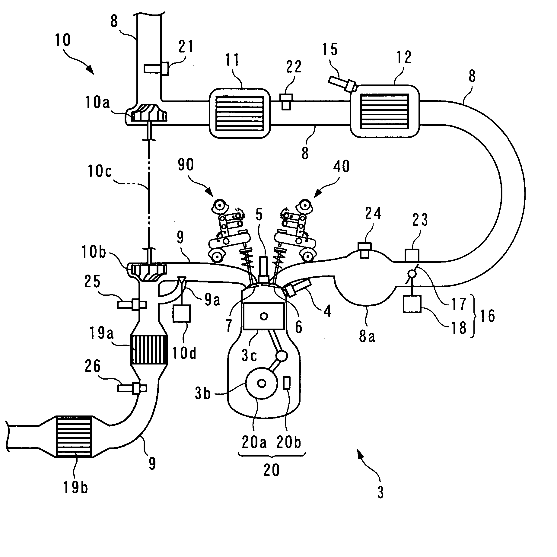
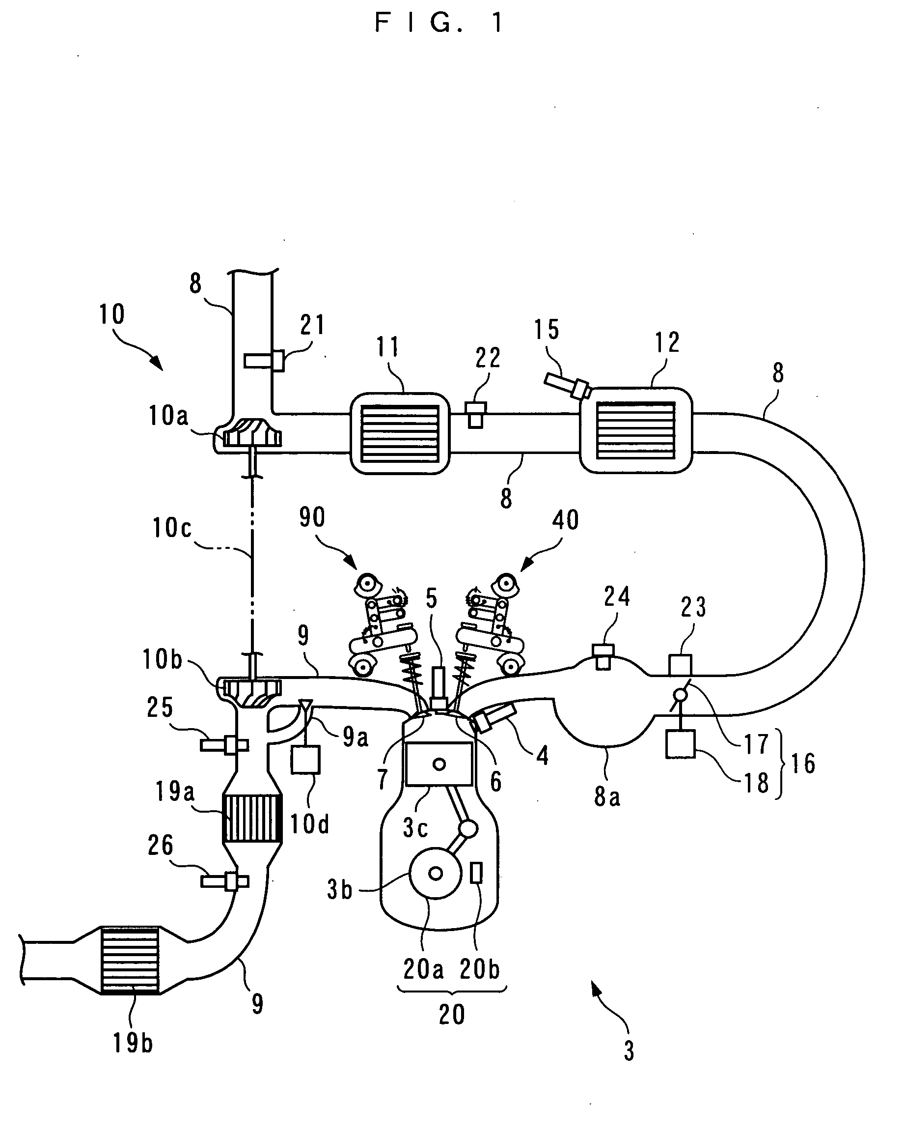
[0161] Hereafter, an intake air amount control system (hereinafter simply referred to as “the control system”) according to an embodiment of the invention will be described with reference to the drawings. Referring first to FIGS. 1 and 2, there is schematically shown the arrangement of an internal combustion engine 3 (hereinafter simply referred to as “the engine 3”) to which the control system 1 according to the present embodiment is applied. FIG. 3 schematically shows the arrangement of the control system 1. As shown in FIG. 3, the control system 1 includes an ECU 2. The ECU 2 carries out various control processes, as described hereinafter, including an intake valve control process for controlling the intake air amount, based on operating conditions of the engine 3.

[0162] The engine 3 is an inline four-cylinder gasoline engine installed on an automotive vehicle, not shown, and has first to fourth cylinders #1 to #4 (a plurality of cylinders) (see FIG. 5). Further, the engine 3 in...


PUM


Abstract

An intake air amount control system for an internal combustion engine, which controls respective amounts of intake air drawn into four cylinders #1 to #4, independently of each other, by variable inter-intake cam phase mechanisms 80, identifies intake air amount variation coefficients Φ#i, based on a model [equation (43)] defining a relationship between an estimated value Gth_est of a TH passing intake air amount and a plurality of simulation values Gcyl_OS#i, such that the estimated value Gth_est becomes equal to the TH passing intake air amount, calculates a target inter-intake cam phase θssi#i_cmd, on a cylinder-by-cylinder basis, according to the identified intake air amount variation coefficients Φ#i (step 81), and calculates control input DUTY_ssi#2 to #4 to the variable inter-intake cam phase mechanisms 80 according to the target inter-intake cam phases θssi#i_cmd (step 75).

Description

FIELD OF THE INVENTION [0001] The present invention relates to an intake-air amount control system for an internal combustion engine, which controls the respective amounts of intake air drawn into a plurality of cylinders. BACKGROUND ART [0002] Conventionally, as an intake air amount control system for an internal combustion engine, there is known one described in Patent Literature 1, for example. The engine is of a four-cylinder type, and is comprised of an electromagnetic valve mechanism provided for each cylinder, for changing the valve-closing timing relative to the valve-opening timing of each cylinder, and a throttle valve mechanism. As described hereinafter, in this intake air amount control system, to control idling speed, the valve-closing timing of each intake valve is controlled via the electromagnetic valve mechanism, whereby the intake air amount is controlled. More specifically, a target intake air amount for feedforward control is calculated according to target engine...

Claims


Application Information

Patent Timeline
Patent Type & Authority Applications(United States)
IPC IPC(8): F02D41/26F01L1/34F02D43/00F01L1/08F01L1/18F01L1/344F01L13/00F01N3/20F01N3/24F02D13/02F02D31/00F02D41/00F02D41/02F02D41/06F02D41/14F02D45/00
CPCF01L1/08Y02T10/42F01L1/3442F01L13/0047F01L2001/34483F01L2201/00F01L2800/00F01L2820/02F02D13/0211F02D13/023F02D13/0246F02D31/002F02D41/0002F02D41/0255F02D41/062F02D41/1403F02D2041/001F02D2041/1416F02D2200/0402Y02T10/18Y02T10/26F01L1/18Y02T10/12Y02T10/40
Inventor YASUI, YUJIYONEKAWA, AKIYUKI
Owner HONDA MOTOR CO LTD
Why Eureka
Try Eureka