

System and method of controlling power to a non-motor load
- Summary
- Abstract
- Description
- Claims
- Application Information
AI Technical Summary
Benefits of technology
Problems solved by technology
Method used
Image

Examples
Embodiment Construction
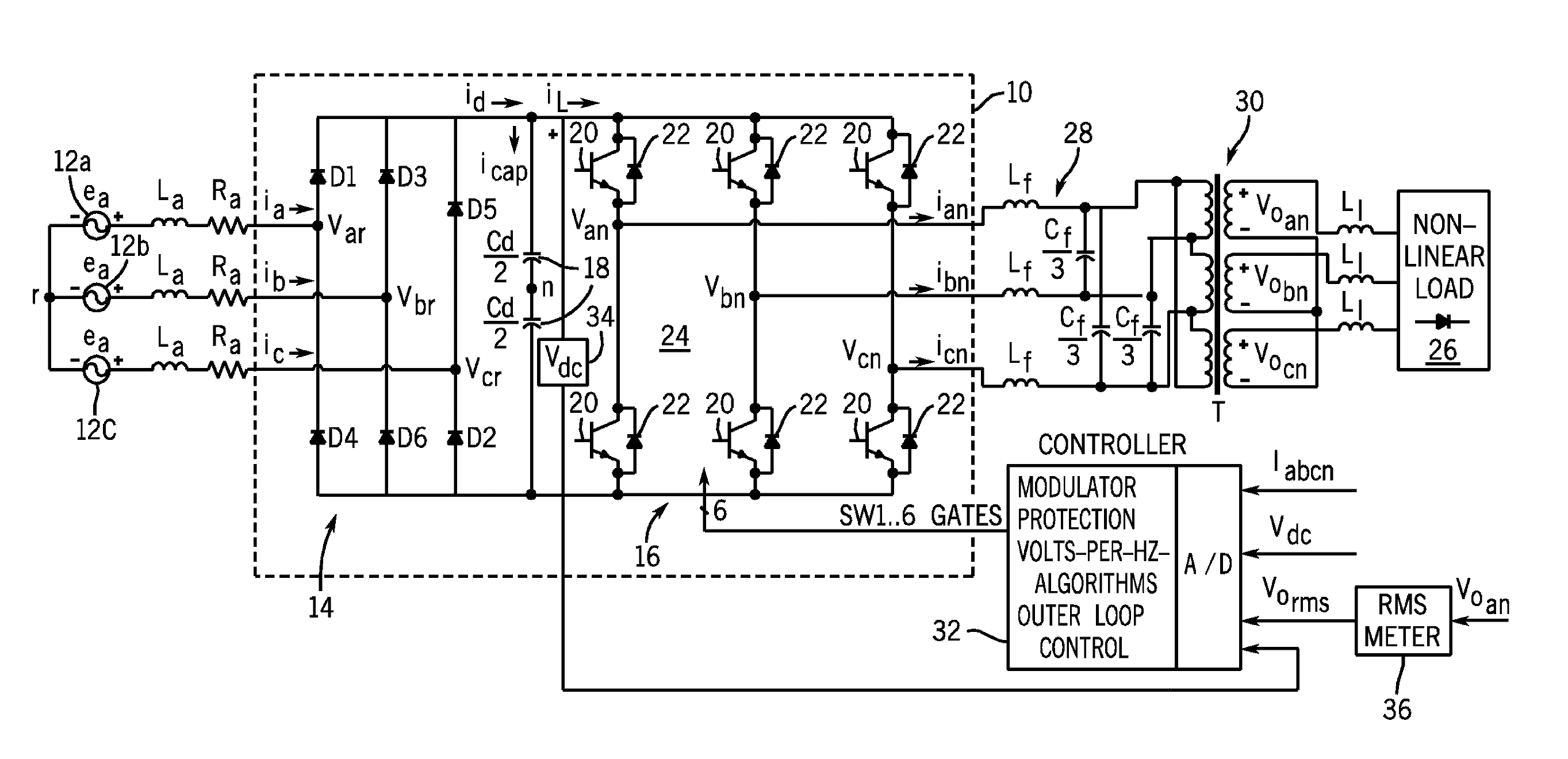
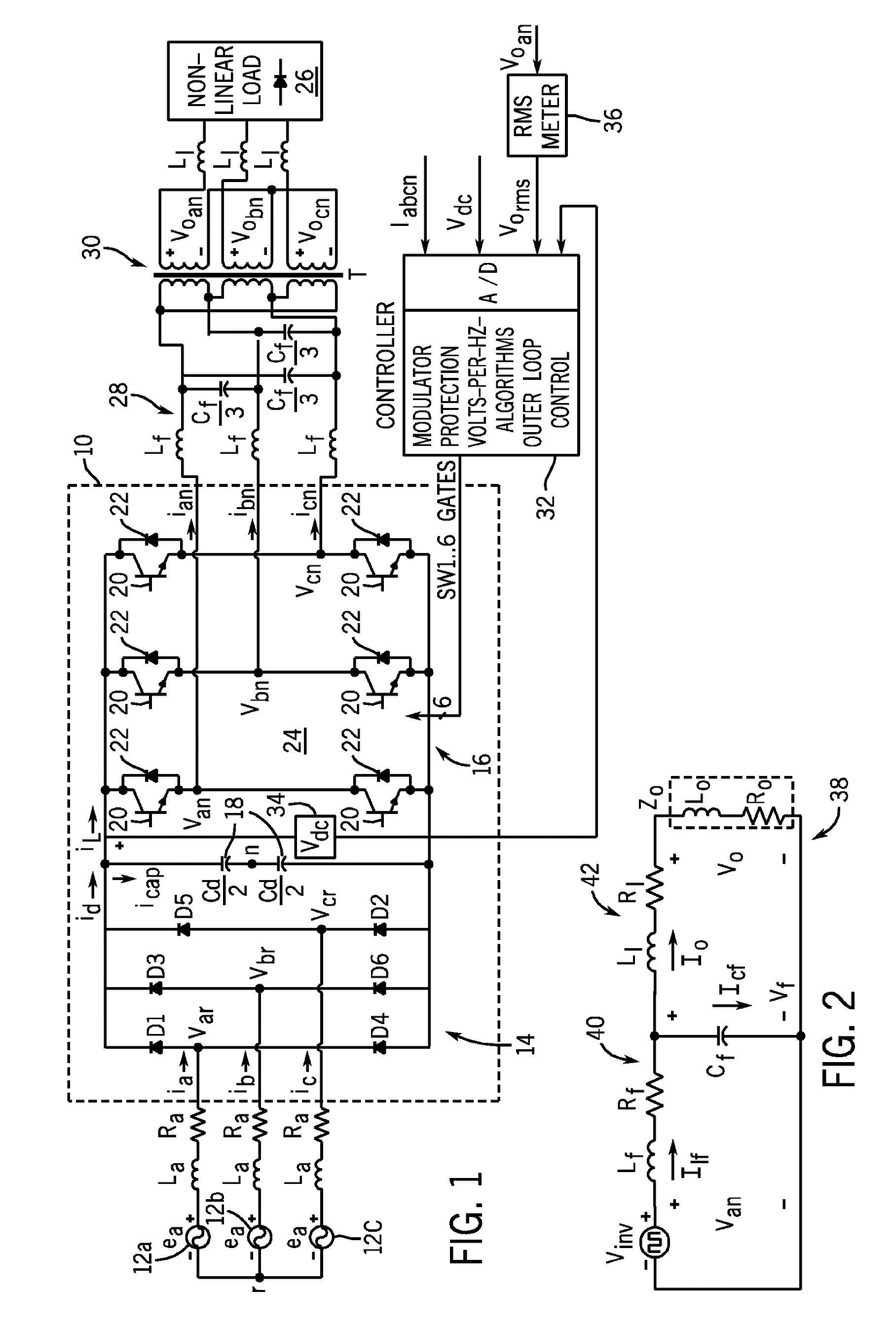
[0033] Referring now to FIG. 1, a power conditioner 8 having an adjustable speed motor drive 10 is shown. The adjustable speed drive (ASD) is designed to receive a three AC power input, rectify the AC input, and perform a DC / AC conversion of the rectified segment into a three-phase alternating voltage of variable frequency and amplitude that is supplied to a load. In a preferred embodiment, the ASD operates according to an exemplary volts-per-hertz characteristic. In this regard, the motor drive provides voltage regulation of ±1% in steady state with less than 3% total harmonic distortion, +0.1 Hz in output frequency, and fast dynamic step load response over a full load range.
[0034] In an exemplary embodiment, a three-phase AC input 12a-12c is fed to a three-phase rectifier bridge 14. The input line impedances are equal in all three phases. The rectifier bridge 14 converts the AC power input to a DC power such that a DC bus voltage is present between the rectifier bridge 14 and a s...
PUM
 Abstract
Description
Claims
Application Information