
Unsynchronized beacon location system and method

a technology of location system and beacon, applied in the direction of signalling system, electric signalling details, instruments, etc., can solve the problems of increasing cost, reducing the operating life between charges, and requiring significant power for gps receiver operation, so as to reduce the possibility of signal collision within the system and the length of packets

Inactive Publication Date: 2007-01-11
SCHURIG ALMA K +3
View PDF41 Cites 94 Cited by
  • Summary
  • Abstract
  • Description
  • Claims
  • Application Information

AI Technical Summary

Benefits of technology

[0012] In view of the foregoing, in accordance with the invention as embodied and broadly described herein, a method and apparatus are disclosed in one embodiment of the present invention as including a system comprising one or more beacons, three or more locators, at least one server, and one or more clients. Each beacon within the system may periodically transmit an electromagnetic signal in the form of a short signal packet (e.g., one to two millisecond in length). The length of the packets may reduce the possibility of signal collisions within the system. Accordingly, in selected embodiments, many beacons may be included within a system.
[0013] The various beacons may control the duration of the off interval (i.e., the time between transmissions) to provide a “duty cycle” permitting classification of the beacon as an intermittent device. This may have two positive effects. First, the duty cycle may minimize power consumption. Second, with appropriate duty cycle selection, beacons in accordance with the present invention may legally transmit within L Band and Ultra High Frequency (UHF) bands, which provide favorable propagation characteristics.

Problems solved by technology

GPS receivers require significant amounts of power for operation.
This increases cost and decreases operating life between charges.
GPS systems require a constellation of expensive satellites.
Additionally, GPS receivers must rely on expensive communications systems (e.g., cellular telephone systems) to report their location.
Accordingly, outside ofthose selected areas, a GPS unit cannot communicate its position to an outside entity.
Moreover, inadvertent and hostile transmitters mayjam the weak satellite signals, thereby denying a GPS receiver correct satellite position data.
Other problems associated with GPS systems include shielding of some of the satellites signals by obstuctions, such as trees, buildings, and other structures.
However, such transmitter systems are limited in their ability to track multiple transmitters.
In some situations, the receiver associated with a transmitter may be unable to receive the “on” signal, and the transmitter may never receive the instruction to transmit.

Method used


Image

  • Unsynchronized beacon location system and method
  • Unsynchronized beacon location system and method
  • Unsynchronized beacon location system and method

Examples


example i

1. EXAMPLE I

[0189] In one selected embodiment, Applicants believe a system 10 in accordance with the present invention may be used by law enforcement to regulate and enforce protective orders (restraining orders).

[0190] Currently, a judicial authority may issue a protective order mandating that a particular individual not come closer that a certain distance to some other person, physical location, or some combination thereof. However, such mandates are difficult to enforce. Law enforcement almost always lacks the resources to monitor such individuals to ensure compliance. Typically, law enforcement only learns that a protective order has been violated after the fact. This is often too late for the person or property the protective order was issued to protect.

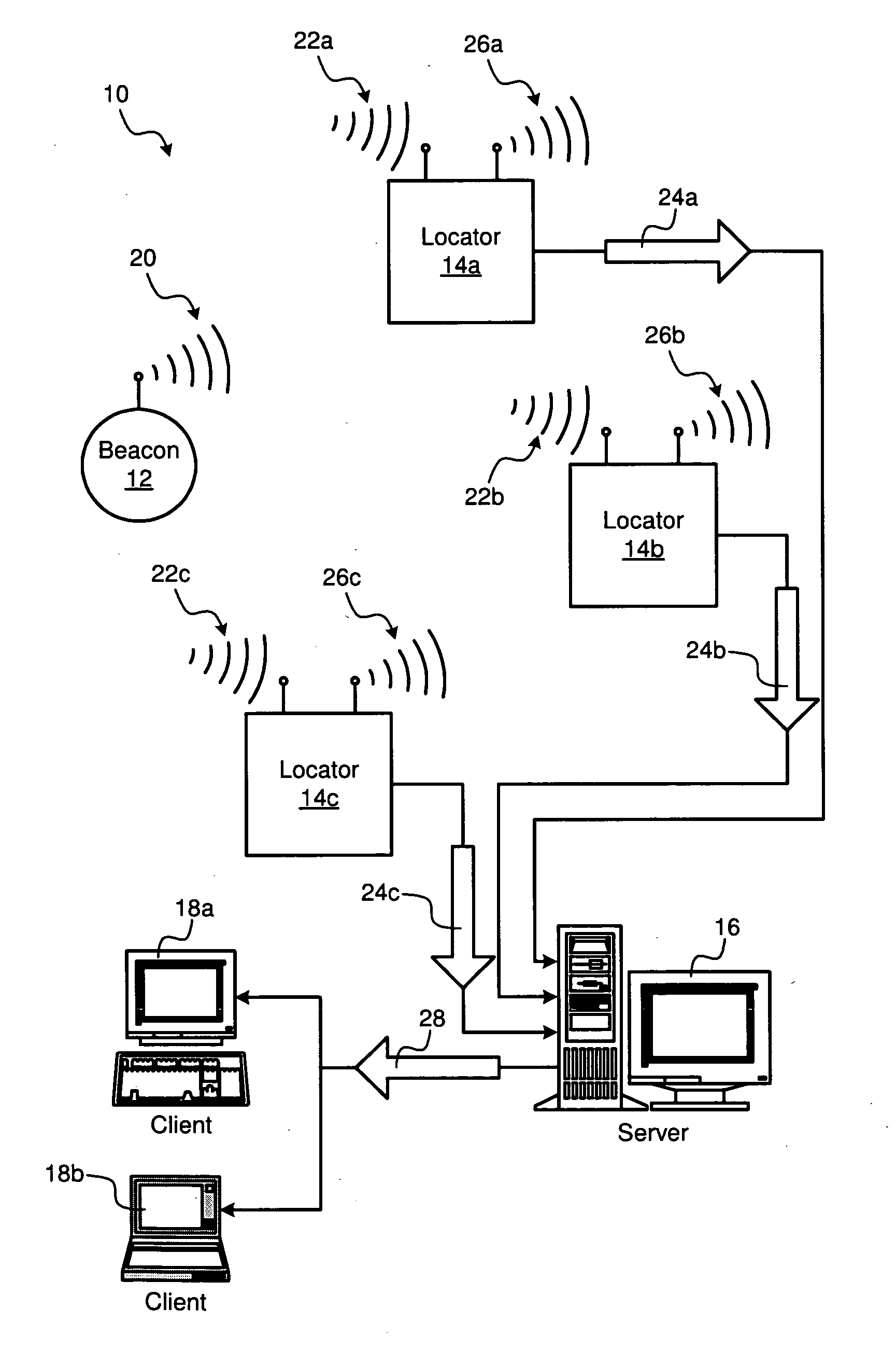
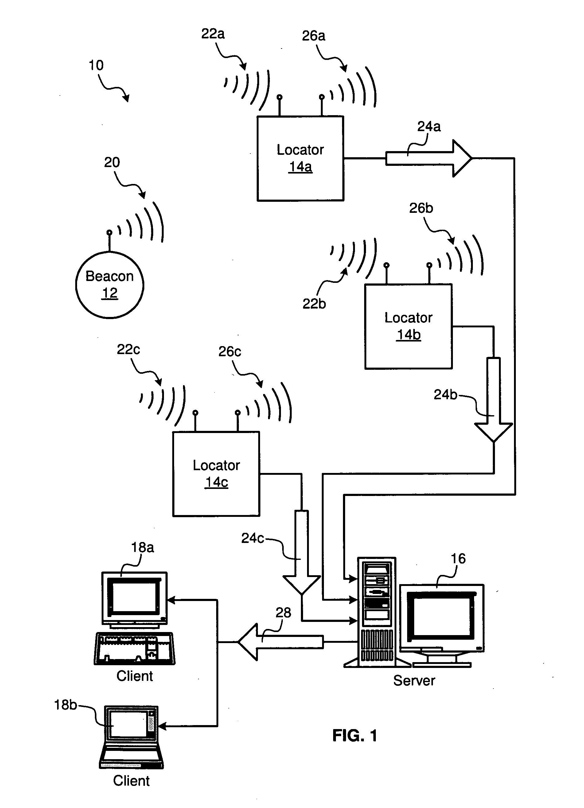
[0191] Using a system 10 in accordance with the present invention, both the person to whom the protective order applies as well as the person or property for which protection is sought may be equipped with beacons 12. Accordin...

example ii

2. EXAMPLE II

[0194] In selected embodiments, a system 10 in accordance with the present invention may be used by law enforcement to regulate parolees. For example, a beacon 12 may be worn by all parolees operating within a system 10. Thus, location information and status information relating to each parolee and corresponding beacon 12 may be collected and reported as desired. Using this information, law enforcement agencies may ensure that parolees do not go to locations likely to give rise to unlawful conduct or otherwise violate the terms of their parol.

example iii

2. EXAMPLE III

[0195] In selected embodiments, a system 10 in accordance with the present invention may be used to locate lost persons. For example, before entering a wilderness area, each person within a group may be equipped with a beacon 12. Accordingly, if any members of the group were to become lost, mobile locators 14 may be deployed to the area. In such an embodiment, a stand-alone computer (e.g., laptop) may function as the server 16 reporting location and status information directly to any operator thereof.

[0196] If desired, beacons 12 for such excursions may be purchased as a nominal cost. As a result, the probability they will be purchased and worn may be greatly increased. The costs of deploying locators 14 and collecting location and status information may then be covered by some responsible entity. Alternatively, the cost of the beacons 12 may be increased somewhat and act as an insurance premium. That is, the revenue collected from sales of the beacons 12 may be used ...


PUM


Abstract

A system comprising a transmitter periodically transmitting a packet via electromagnetic radiation. The packet may be encoded with information and have a length measured in time. The system may further include a receiver comprising an antenna converting incident electromagnetic radiation to an analog electrical current, an analog-to-digital converter receiving the analog electrical current and producing a digital representation thereof, and first and second buffers. Each of the buffers may have a capacity of at least two times the length of the packet. The first and second buffers may store respective first and second copies of the digital representation. The first copy may be offset in time from the second copy by at least the length of the packet.

Description

RELATED APPLICATIONS [0001] This application claims the benefit of co-pending U.S. Provisional Patent Application Ser. No. 60 / 697,914, filed on Jul. 7, 2005 for LOCATION SYSTEM AND METHOD.BACKGROUND [0002] 1. The Field of the Invention [0003] This invention relates to locating and tracking systems and more particularly to novel systems and methods for locating people and physical assets as a function of time. [0004] 2. The Background Art [0005] Various systems have been developed to determine the position of objects and people. These systems have been based on a variety of communications technologies. For example, a Global Positioning System (GPS) requires a portable receiver. Each such receiver determines its position by referencing itself to the transmitted signals emitted by an array of earth-orbiting satellites. The receiver reports the calculated position via a display to a user. [0006] For remote reporting of a receiver's position, a GPS receiver must transmit its position. Th...

Claims


Application Information

Patent Timeline
IPC IPC(8): G01S1/00G08B1/08H04B7/185H04Q7/00
CPCG01S5/0215G01S5/06G01S5/0226G01S5/0221
Inventor SCHURIG, ALMA K.ANDERSON, KEITHMILLS, DAVID L.GARDNER, DAVID J.
Owner SCHURIG ALMA K
Features
  • Generate Ideas
  • Intellectual Property
  • Life Sciences
  • Materials
  • Tech Scout
  • Unparalleled Data Quality
  • Higher Quality Content
  • 60% Fewer Hallucinations
Learn More