
Method for controlling sagging of a power transmission cable

a technology of power transmission cable and bare conductor, which is applied in the field of electric power transmission, can solve the problems of slowing down the technology's acceptance, low modulus of elasticity of supporting cores and achieves low elasticity with temperature, low cost, and low modulus of elasticity.

Inactive Publication Date: 2007-01-11
GIFT TECH LLC
View PDF34 Cites 14 Cited by
  • Summary
  • Abstract
  • Description
  • Claims
  • Application Information

AI Technical Summary

Benefits of technology

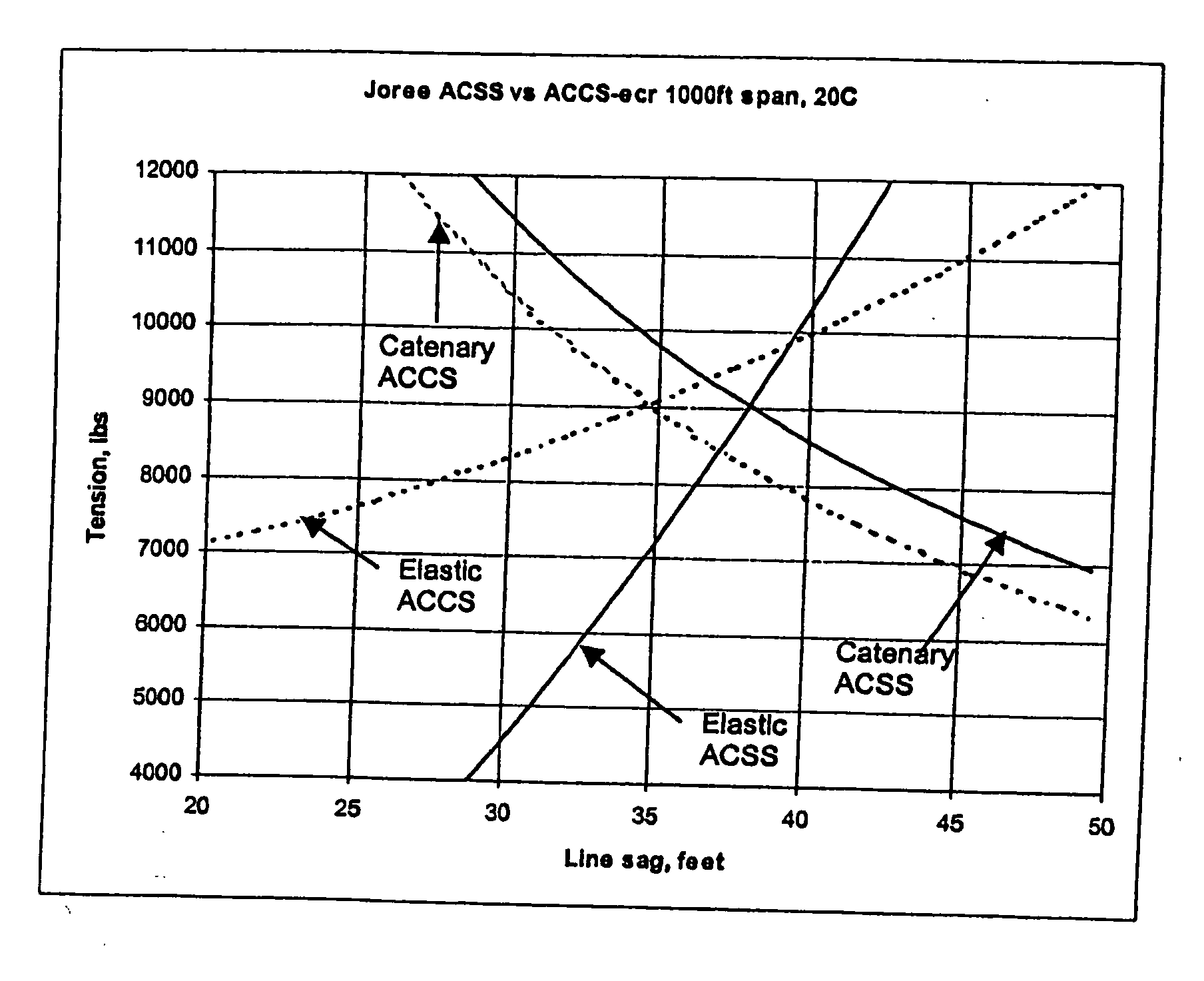
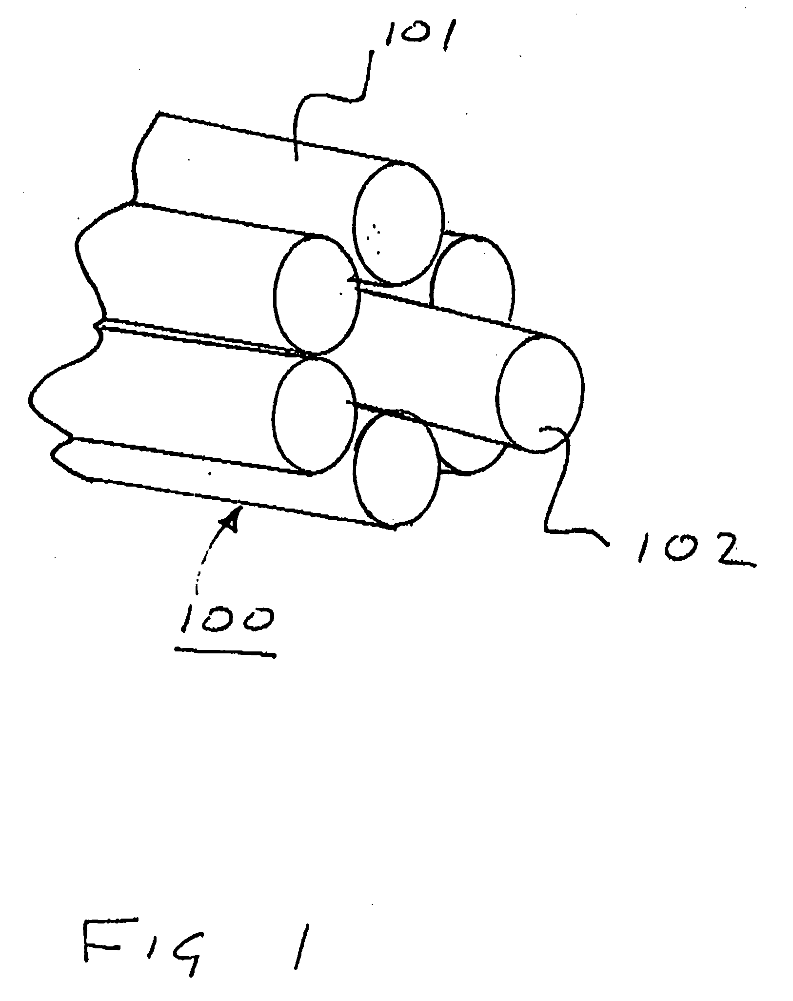
[0014] It is an exemplary embodiment of the invention, a bare conductor cable and method for stringing the same to have a low sag with temperature and a lower cost are provided. In one exemplary embodiment, a bare conductor cable with a composite core is provided. The core has a lower modulus of elasticity than an equivalent core made from steel. Using a tensioning method, most of the initial tension during stringing and sagging operations is placed onto the core.

Problems solved by technology

However, composite core technology has a number of difficulties that have slowed the technology's acceptance into the mix of technology solutions available to the utility companies.
Among these difficulties is the low modulus of elasticity of the supporting cores.
Thus it would appear to those skilled in the art that apart from the higher ultimate strength and the lower thermal coefficient of expansion the low modulus of elasticity can seriously undermine the value of the composite technologies, particularly the value of glass fiber.
Indeed the low modulus of elasticity for a glass fiber core suggests that to get to the higher ultimate strength of core the sag on a transmission line would be unacceptably large.

Method used


Image

  • Method for controlling sagging of a power transmission cable
  • Method for controlling sagging of a power transmission cable
  • Method for controlling sagging of a power transmission cable

Examples


Embodiment Construction

[0024] In FIGS. 1 through 4, like reference numerals refer to like components in the various views.

[0025] Composite core technologies such as glass fiber and carbon fiber in resin have a number of advantages for use as a conductor support core. These advantages include, among other things, low thermal expansion, low weight, low creep, high internal damping, high elasticity, high corrosion resistance, and high ultimate tensile strength.

[0026] Glass fiber also has the advantage that it is of a similar cost to steel while carbon is more expensive. Thus, a high ampacity high temperature glass fiber composite supported cable, Aluminum Conductor Composite Supported, ACCS, cable having a glass fiber composite will enable a transmission system with greater ground clearance under high current load, high resistance to Aeolian vibration, and longer life, for no extra cost.

[0027] In an exemplary embodiment, the invention is characterized by a bare conductor cable with a composite core. The c...


PUM


Abstract

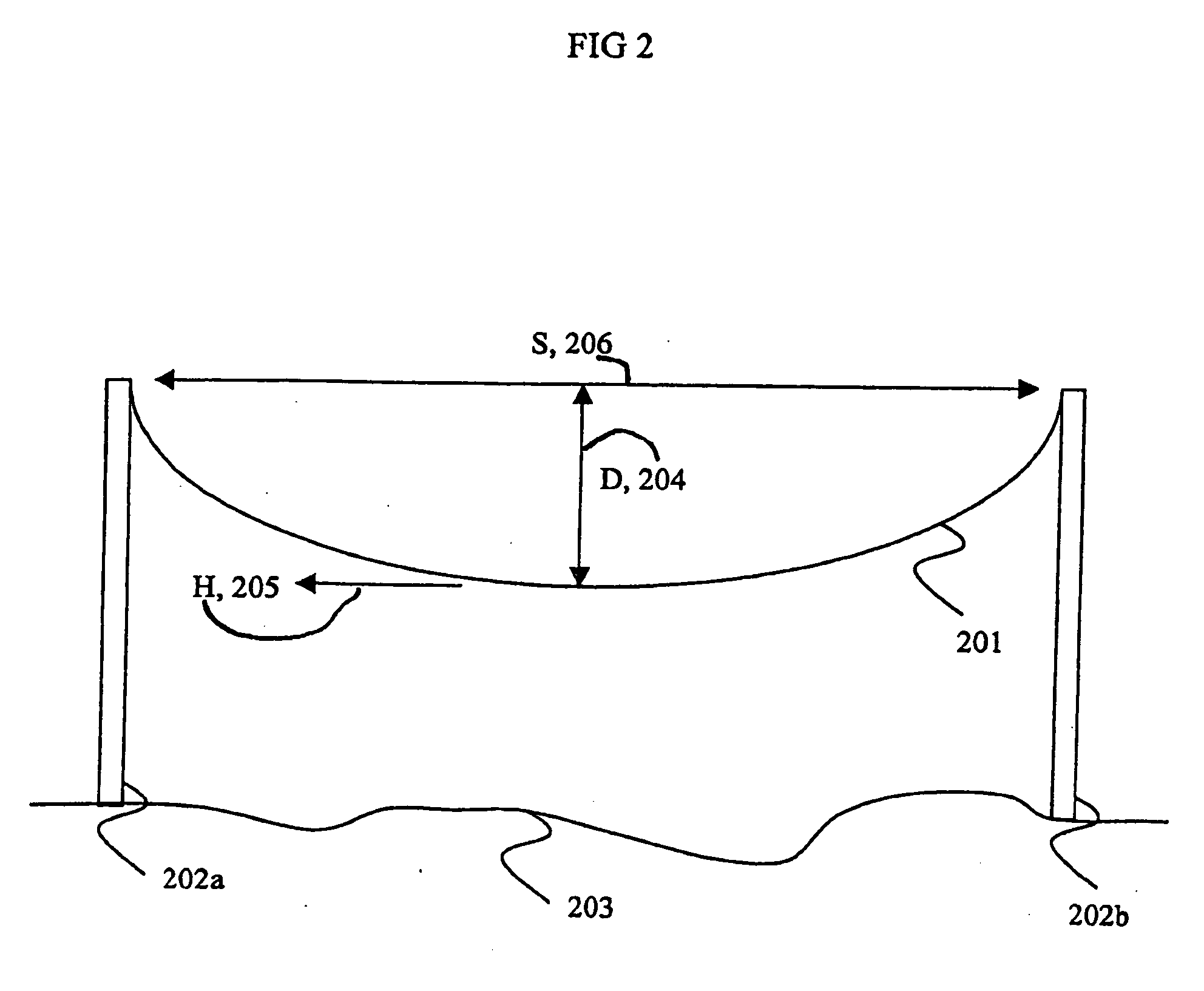
A method is provided for controlling the sagging of a power transmission cable hang between two towers. The cable has a first supporting portion and a second conductive portion. The method includes a first act of mounting the cable between the two towers, such that when mounted between the towers the cable has a cable load. The method further includes a second act of stretching the first portion to have a cable sag less than a desired sag, a third act of releasing at least some of the tension to obtain the desired sag, and a fourth act calculating a load magnitude carried by the first portion. If the load magnitude is less than a desired load magnitude the method includes repeating the second, third and fourth acts until the load magnitude is at the desired level.

Description

CROSS-REFERENCE TO RELATED APPLICATION(S) [0001] This application is based upon and claims priority on U.S. Provisional Application No. 60 / 698,429 filed on Jul. 11, 2005, the contents of which are fully incorporated herein by reference.TECHNICAL FIELD [0002] The present invention relates generally to electrical power transmission, and more particularly to a high temperature bare conductor cable with an elastic or composite supporting core for electrical power transmission lines and a method for tensioning the conductor cable, and still more particularly to a conductor cable incorporating a composite supporting core with a low temperature coefficient of expansion, and still more particularly to a tensioning method for a composite core cable that reduces the sag induced in the cable by thermal expansion. BACKGROUND INFORMATION AND DISCUSSION OF RELATED ART [0003] Electrical cables used in high voltage overhead transmission lines are typically bare conductors of aluminum with a central...

Claims


Application Information

Patent Timeline
IPC IPC(8): G02B6/00
CPCH02G1/04H02G7/04H02G7/02
Inventor BROWNING, RAYMOND
Owner GIFT TECH LLC
Learn More