Method for labeling fabrics and heat-transfer label well-suited for use in said method cross-reference to related applications

a technology of fabric and label, applied in the field of fabric labeling, can solve the problems of garment itself, clothing damage, wearer irritation, loss of information contained on the label,

Inactive Publication Date: 2007-01-11
AVERY DENNISON CORP
View PDF52 Cites 68 Cited by
  • Summary
  • Abstract
  • Description
  • Claims
  • Application Information

AI Technical Summary

Problems solved by technology

Unfortunately, the presence of a permanent care label on certain articles, such as undergarments or other garments in which the label is in direct contact with the wearer's skin, can become irritating to the wearer.
However, as can readily be appreciated, such a practice not only results in a loss of the information contained on the label but the act of cutting or ripping the permanent care label from the garment can also result in significant damage to the garment, itself.
One problem with the heat-transfer approach described above is that the transfer portion, once applied to a garment, must be allowed to cool prior to the peeling away of the support portion therefrom.
If such a period of time is not provided to permit the heated transfer portion to cool, the release of the transfer portion from the support portion will not be clean, and the transfer portion will not transfer completely to the garment.
This is problematic because the cooling step, which can have a duration in the range of several seconds up to one or more minutes, adds time to the labeling process, thereby limiting the throughput of the process.

Method used


Image

  • Method for labeling fabrics and heat-transfer label well-suited for use in said method cross-reference to related applications
  • Method for labeling fabrics and heat-transfer label well-suited for use in said method cross-reference to related applications
  • Method for labeling fabrics and heat-transfer label well-suited for use in said method cross-reference to related applications

Examples


first embodiment

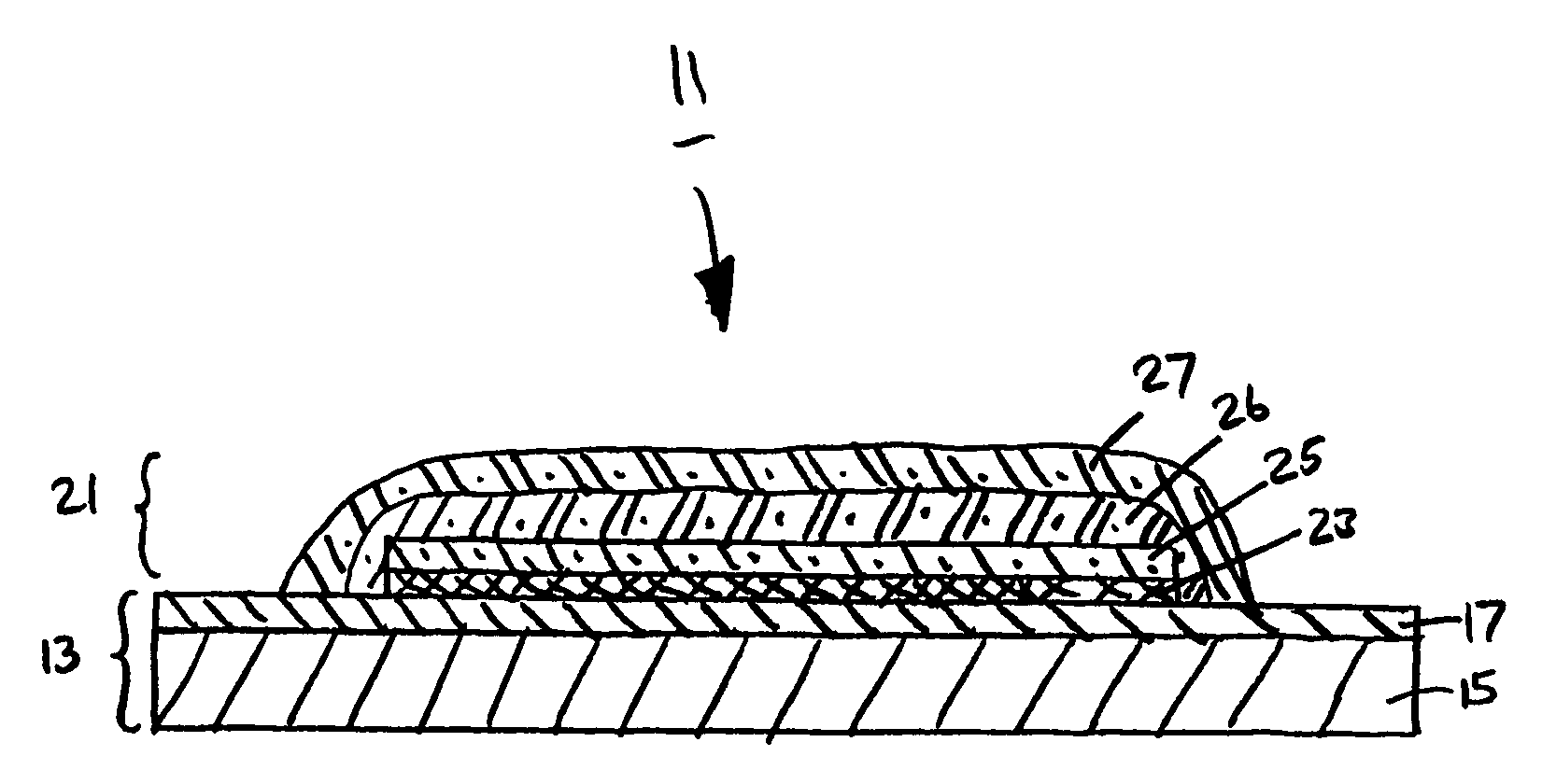
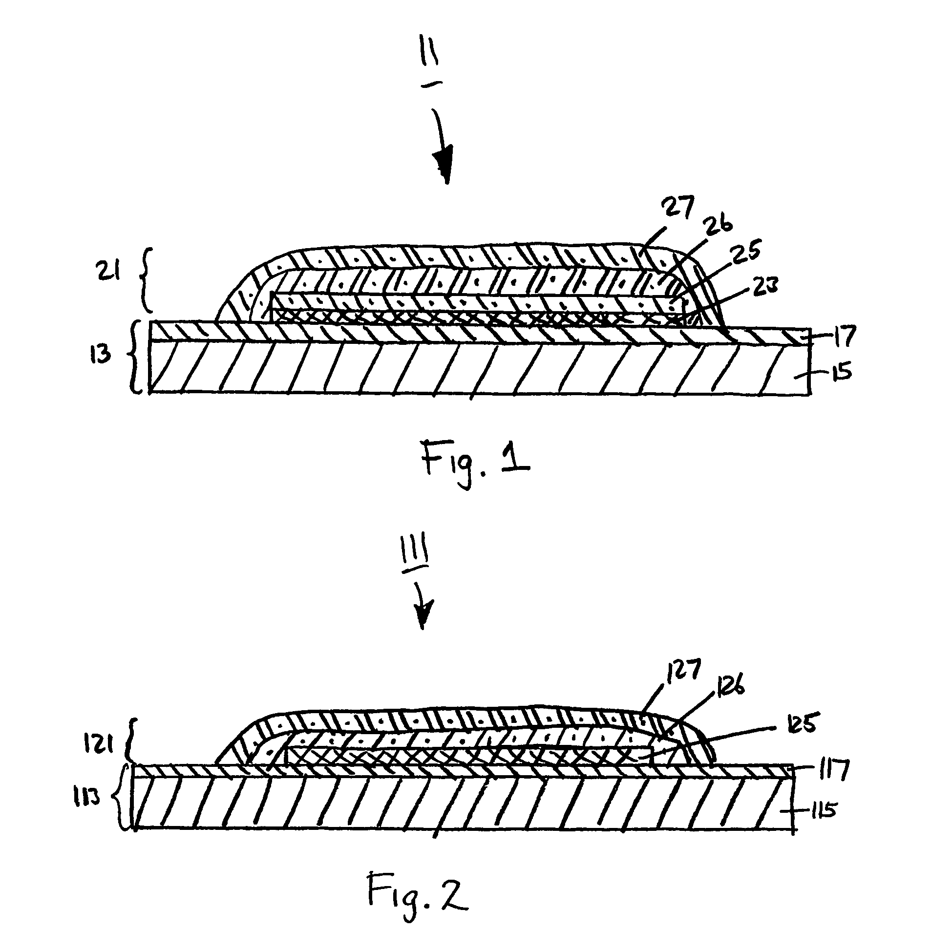
[0043] Referring now to FIG. 1, there is shown a schematic section view of a heat-transfer label well-suited for use in labeling articles of fabric, said heat-transfer label being constructed according to the teachings of the present invention and being represented generally by reference numeral 11.

[0044] Label 11 comprises a support portion 13. Support portion 13, in turn, comprises a carrier 15. Carrier 15 may be a paper substrate, a polymer-coated paper substrate, or a polymer film substrate. Preferably, carrier 15 is a polymer film substrate having a glass transition temperature in the range of 60° C. to 250° C. and having a storage modulus in the range of 1.0×10¹⁰ dynes / cm2 to 2.0×10¹⁰ dynes / cm2 at ambient temperature and a storage modulus in the range of 5.0×10⁷ to 1.5×10¹⁰ dynes / cm2 at 100° C. Examples of materials particularly preferred for use as carrier 15 include polyester films, particularly polyethylene terephthalate (PET) films and poly(ethylene 2,6-naphthalene dicarbo...

second embodiment

[0084] Referring now to FIG. 2, there is shown a schematic section view of a heat-transfer label well-suited for use in labeling articles of fabric, said heat-transfer label being constructed according to the teachings of the present invention and being represented generally by reference numeral 111.

[0085] Heat-transfer label 111 comprises a support portion 113, support portion 113 comprising a carrier 115 and a release layer 117. Carrier 115 is identical carrier 15 of label 11, and release layer 117 is identical to release layer 17 of label 11.

[0086] Heat-transfer label 111 also comprises a transfer portion 121 (it being understood that, even though only a single transfer portion 121 is shown on a slightly oversized support portion 113 in FIG. 2, one need not position only one transfer portion 121 per support portion 113, but rather, one may space apart at regular intervals a plurality of identical or different transfer portions 121 on an elongated common web of support portion 11...

third embodiment

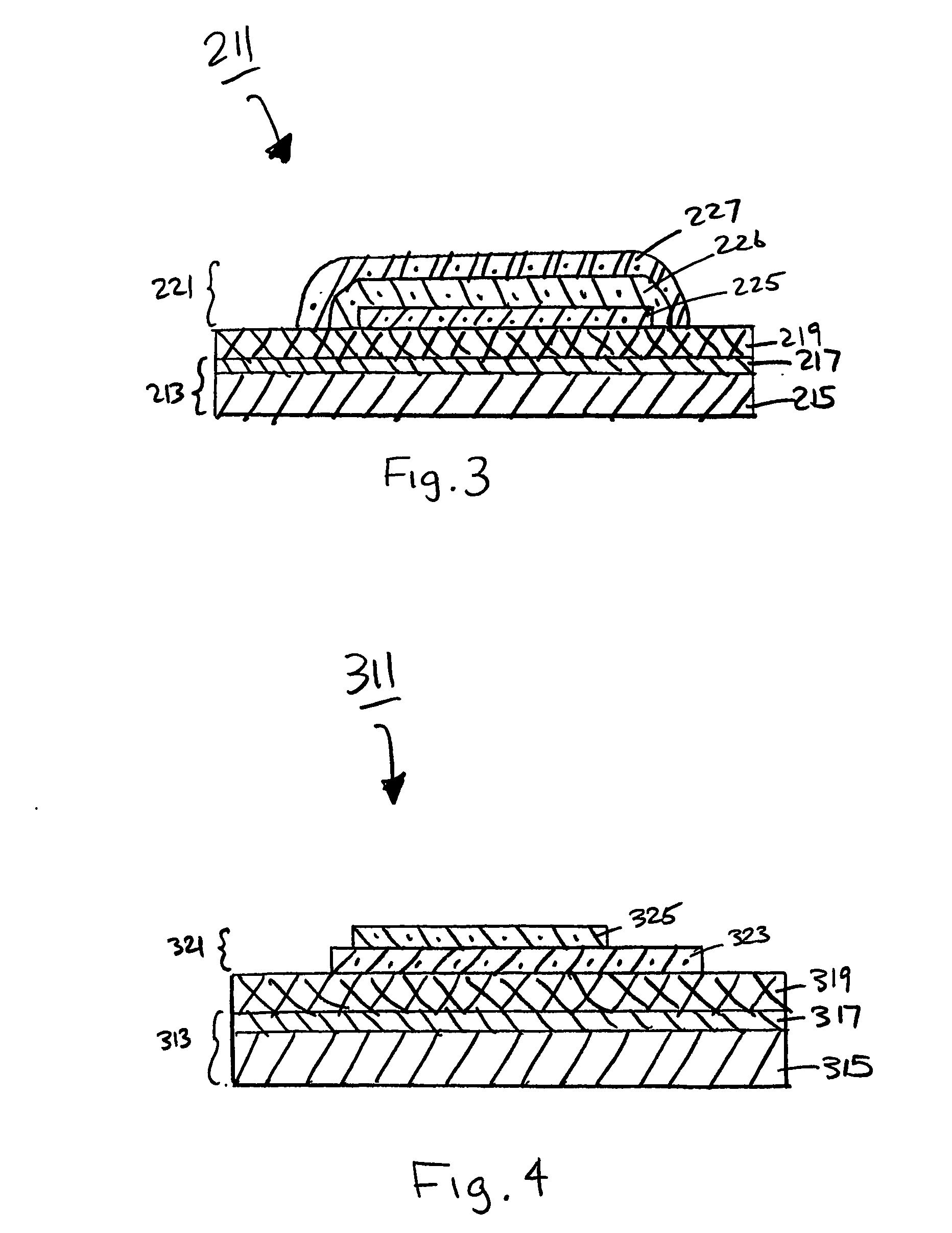
[0095] Referring now to FIG. 3, there is shown a schematic section view of a heat-transfer label well-suited for use in labeling articles of fabric, said heat-transfer label being constructed according to the teachings of the present invention and being represented generally by reference numeral 211.

[0096] Heat-transfer label 211 comprises a support portion 213, support portion 213 comprising a carrier 215 and a release layer 217. Carrier 215 is identical to carrier 15 of label 11, and release layer 217 is identical to release layer 17 of label 11.

[0097] Heat-transfer label 211 also comprises a wax layer 219, wax layer 219 overcoating release layer 217 of support portion 213. Wax layer 219, which serves to facilitate the release of the transfer portion to be described below from support portion 213, preferably has a thickness of about 1 to 20 microns, more preferably about 4 to 15 microns, and preferably has a melting point of about 60 to 130° C., more preferably about 80 to 120° C...


PUM

PropertyMeasurementUnit
surface roughnessaaaaaaaaaa

Abstract

A method for labeling fabrics, such as fabric garments, and a heat-transfer label (311) well-suited for use in said method. In one embodiment, the heat-transfer label (311) comprises (i) a support portion (313), the support portion (313) comprising a carrier (315) and a release layer (317); (ii) a wax layer (319), the wax layer overcoating the release layer (317); and (iii) a transfer portion (321), the transfer portion (321) comprising an adhesive layer (323) printed directly onto the wax layer (319) and an ink design layer (325) printed directly onto the adhesive layer (323). Each of the adhesive layer (323) and the ink design layer includes a non-cross-linked PVC resin. The ink design layer may be screen printed onto the adhesive layer (323) or may be printed onto the adhesive layer (323) using thermal transfer printing, ink jet printing or laser printing.

Description

CROSS-REFERENCE TO RELATED APPLICATIONS [0001] The present application claims the benefit under 35 U.S.C. 119(e) of U.S. Provisional Patent Application Ser. No. 60 / 430,216, filed Dec. 2, 2002, and U.S. Provisional Patent Application Ser. No. 60 / 453,661, filed Mar. 11, 2003, both of which are incorporated herein by reference.BACKGROUND OF THE INVENTION [0002] The present invention relates generally to the labeling of fabrics and relates more particularly to the labeling of fabric garments. [0003] It is customary for manufacturers of garments and other finished fabrics (e.g., towels, bed linens, tablecloths, etc.) to attach thereto one or more label displaying various items of information, such as article size, fiber content, instructions for care, and the manufacturer's name or trademark. Such labels, which are to be contrasted with hanging price tags and the like, are typically not intended to be removed by the consumer after the purchase of the article, but rather, are intended to ...

Claims


Application Information

Patent Timeline
Patent Type & Authority Applications(United States)
IPC IPC(8): B32B7/12B32B7/06C09J7/02B32B27/00B41M3/14B41M5/00B41M5/025B41M5/50B41M5/52B44C1/17B65C5/04D06P5/24D06Q1/12G09F3/02
CPCB32B27/00Y10T428/2817B41M5/506B41M5/508B41M5/5254B44C1/1712B65C5/04D06H1/02D06P1/004D06P5/003D06P5/007D06Q1/12G06K19/027G09F3/00G09F3/02G09F3/10Y10S428/913Y10S428/914Y10T428/2822Y10T428/24802Y10T428/2848Y10T428/2813Y10T428/2839Y10T428/2826B41M3/14G09F3/04G09F2003/025B32B7/06B32B7/12B32B27/08B32B27/32B32B27/36B32B27/40B32B2307/302B32B2317/12B32B2323/10B32B2367/00B32B2375/00B32B2519/02
Inventor TSAI, KUOLIHHSEIH, DONG-TSAISHU, LIEDWARDS, DAVIDMORGENTHAU, ALANCHIAO, YI-HUNGHE, XIAO-MINGSASAKI, YUKIHIKOFERGUSON, SCOTT
Owner AVERY DENNISON CORP
Why Eureka
Try Eureka