
Distance measuring device, distance measuring method and distance measuring program

a technology of distance measurement and distance measurement method, applied in the direction of measurement device, using reradiation, instruments, etc., can solve the problems of limited measurement accuracy, limited outdoor use, difficult measurement of short distance, etc., and achieve the effect of high accuracy of measurement to a short distan

Active Publication Date: 2007-01-18
UNIVERSITY OF TOKUSHIMA +1
View PDF4 Cites 22 Cited by
  • Summary
  • Abstract
  • Description
  • Claims
  • Application Information

AI Technical Summary

Benefits of technology

[0055] An object of the present invention is to provide a distance measuring device, a distance measuring method and a distance measuring program that allow highly accurate measurement to a short distance, even in a narrow emission frequency bandwidth.
[0056] Another object of the present invention is to provide a distance measuring device, a distance measuring method and a distance measuring program that allow accurate measurement of distance to a moving object.
[0075] According to the present invention, a distance measuring device that allows highly accurate distance measurement from 0 m, even in a limited transmission frequency bandwidth, can be provided.

Problems solved by technology

Though the two methods both have high measurement accuracy, the methods respectively have the following problems.
Therefore, bandwidth is insufficient for outdoor-use of an FMCW microwave type level meter, so that the measurement accuracy is limited and measurement of short distance is difficult.
Therefore, in this case also, outdoor use is limited because of the restriction of bandwidth defined by the Radio Law, and measurement of short distance is difficult, as shorter electric pulses cannot be used.
The two methods of measurement use wide bandwidth, and therefore, these cannot be used as the specified low power radio station as classified by the Radio Law.
When the output power of emission signal is made lower, however, the power of the reflected signal also comes to be very low.
This leads to a problem that measurement of long distance comes to be highly susceptible to the influence of noise.
As the distance d becomes smaller, two local maximums come to interfere with each other, making the waveform irregular.
Specifically, the conventional distance measuring device has a problem of increased measurement error at shorter distance, which derives from the influence of the local maximum appearing in the region where x is negative on the local maximum appearing in the region where x is positive (hereinafter also referred to the negative frequency influence).
When the conventional distance measuring device is used as the specified low power radio station, the available frequency bandwidth is limited by the laws like the Radio Law.
Therefore, as in the example of FIG. 13, the result of measurement involves significant error in measuring a position at a short distance of 2 m or shorter.
One possible cause of the error is that window length of a window function for Fourier transform is not an integer multiple of the waveform of reception power signal p(f, 0).
Further, at a middle to long distance, measurement error occurs when the position of the object Mk changes slightly, even though the reception power signal p(f, 0) has periodicity.
Such a multi-processing, however, includes a plurality of Fourier transform processes, and therefore, takes considerably long time.
Thus, it is not suitable for an application that requires quick response.
The distance measuring device shown in FIG. 10 further has a problem that the result of measurement has some error when the object of measurement Mk is moving on an axis of measurement (x-axis) at a constant speed.
When the periodicity becomes longer, periodicity of at least one period is lost in the reception power signal p(f, 0) in the transmission frequency bandwidth fw regardless of the sweeping direction, so that the measurement error caused by the negative frequency influence mentioned above increases.
It can be seen, however, that the measurement error increases when the speed of movement increases, exceeding this range.
Specifically, in the conventional distance measuring device, only the local maximum of the region where x is positive is uniformly extracted in the waveform of profile magnitude |P(x)|, and therefore, it is difficult to accurately detect the object of measurement Mk that is in the region where x is negative and is moving away at high speed.

Method used


Image

  • Distance measuring device, distance measuring method and distance measuring program
  • Distance measuring device, distance measuring method and distance measuring program
  • Distance measuring device, distance measuring method and distance measuring program

Examples


Embodiment Construction

[0091] In the following, embodiments of the present invention will be described in detail with reference to the figures. In the figures, the same reference characters denote the same or corresponding portions.

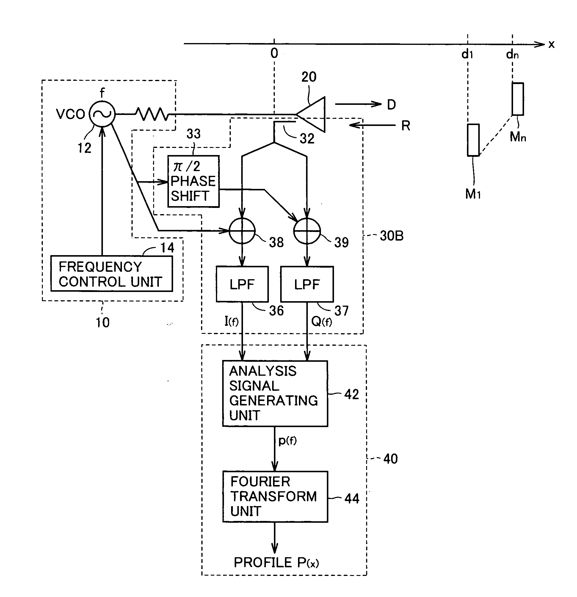
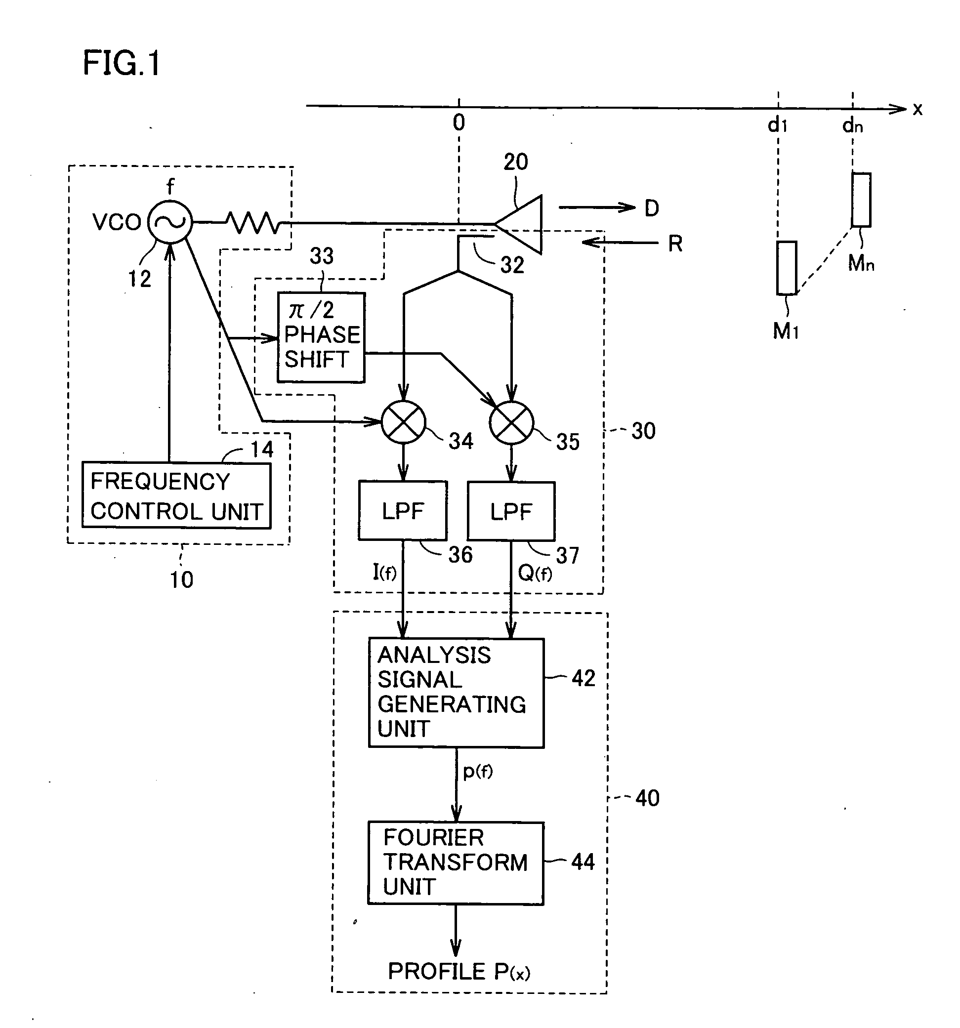
[0092]FIG. 1 is a circuit diagram showing a basic configuration of the distance measuring device in accordance with an embodiment of the present invention.

[0093] Referring to FIG. 1, the distance measuring device includes: a sending source 10 sending a transmission signal having a constant transmission frequency fw a transmission unit 20 emitting an electromagnetic wave of the same frequency f as the sent transmission signal; a detecting unit 30 detecting electromagnetic waves (hereinafter also referred to as reflected waves R) that are the electromagnetic wave output from transmission unit 20 (hereinafter also referred to as traveling wave D) reflected by objects of measurement M1 to Mn; and a signal processing unit 40 processing the reflected waves R detected by detecting u...


PUM


Abstract

A transmission unit emits an electromagnetic wave having the same frequency f as an output signal from a sending unit in a direction of a measurement axis. A detecting unit performs synchronous detection on a reflected wave detected by a directional coupler by an in-phase signal and a quadrature signal of the transmission signal, and by extracting DC component from the detection signal, detects the in-phase component and quadrature component of the reflected wave. An analysis signal generating unit mixes the in-phase component and quadrature component of the reflected wave and signals having periodicity corresponding to a prescribed distance, and using only one of the resulting side bands, generates an analysis signal. Fourier transform unit finds distance to the object of measurement from a profile obtained by Fourier transform of the analysis signal.

Description

BACKGROUND OF THE INVENTION [0001] 1. Field of the Invention [0002] The present invention relates to a distance measuring device, a distance measuring method and a distance measuring program. More specifically, the present invention relates to a distance measuring device, a distance measuring method and a distance measuring program for measuring distance to an object of measurement using an electromagnetic wave emitted to the object. [0003] 2. Description of the Background Art [0004] Methods of measuring distance to an object of detection utilizing a microwave generally used at present is roughly classified into FMCW (Frequency Modulated Continuous Wave) based method and pulse-radar based method. [0005] In the FMCW based method, frequency-swept continuous waves are sent, and from frequency difference between the emitted signal and a reflected signal, the distance to the object of detection is found (see, for example, Japanese Patent Laying-Open No. 07-159522). [0006] In pulse radar,...

Claims


Application Information

Patent Timeline
IPC IPC(8): G01S13/08
CPCG01S2007/356G01S13/36G01S7/356G01S13/08
Inventor IRITANI, TADAMITSUWAKABAYASHI, KAZUHIRO
Owner UNIVERSITY OF TOKUSHIMA
Learn More