
Ink jet recording head having piezoelectric element and electrode patterned with same shape and without pattern shift therebetween

a piezoelectric element and recording head technology, applied in printing and other directions, can solve the problems of affecting the efficiency of jet ink, affecting the effect of jet characteristic, and difficult to use pzt thin film to jet ink more than pzt bulk pzt, so as to achieve the effect of effective electric field application, sufficient jet characteristic, and stably providing

Inactive Publication Date: 2007-01-18
SEIKO EPSON CORP
View PDF21 Cites 5 Cited by
  • Summary
  • Abstract
  • Description
  • Claims
  • Application Information

AI Technical Summary

Benefits of technology

[0014] It is therefore an object of the invention to provide an ink jet recording head capable of effectively applying an electric field to a piezoelectric thin film and stably providing a sufficient jet characteristic with no pattern shift between the piezoelectric thin film and an electrode.
[0021] Further, in the present invention, the piezoelectric thin film is formed via the diaphragm on the ink chamber not reaching the outside of the ink chamber and that the portion of the diaphragm in the area not attached to the piezoelectric thin film is thinner than the portion of the diaphragm in the area attached to the piezoelectric thin film. Therefore, the diaphragm portion in the area not attached to the piezoelectric thin film easily bends, so that a high-definition, high-accuracy ink jet recording head can be provided while providing a sufficient ink jet amount in a small diaphragm area without increasing the piezoelectric thin film area.

Problems solved by technology

In the conventional ink jet recording head previously described, a pattern shift occurs between the PZT element and the upper electrode and even if they are patterned with the same pattern, it is feared that a leak between the upper electrode and the common electrode will occur due to a pattern shift between the PZT element and the upper electrode.
In doing so, it is feared that the electric field on the upper electrode 5 side will not be applied to the piezoelectric part where the upper electrode does not exist, worsening the efficiency for jetting ink.
Generally, the piezoelectric constant of the PZT thin film is only a half to a third of the piezoelectric constant of bulk PZT and if only PZT elements differ and other design values are the same, it is difficult to use the PZT thin film to jet ink more than ink with bulk PZT.
According to this method, an amount of ink required for printing can be jetted, but if the PZT thin film area increases, ink jet recording head cannot be formed in high density and high-definition print quality cannot be provided.

Method used


Image

  • Ink jet recording head having piezoelectric element and electrode patterned with same shape and without pattern shift therebetween
  • Ink jet recording head having piezoelectric element and electrode patterned with same shape and without pattern shift therebetween
  • Ink jet recording head having piezoelectric element and electrode patterned with same shape and without pattern shift therebetween

Examples


Embodiment Construction

[0072] Referring now to the accompanying drawings, there are shown preferred embodiments of the invention. First, a first embodiment of the invention will be discussed based on FIGS. 1 to 8.

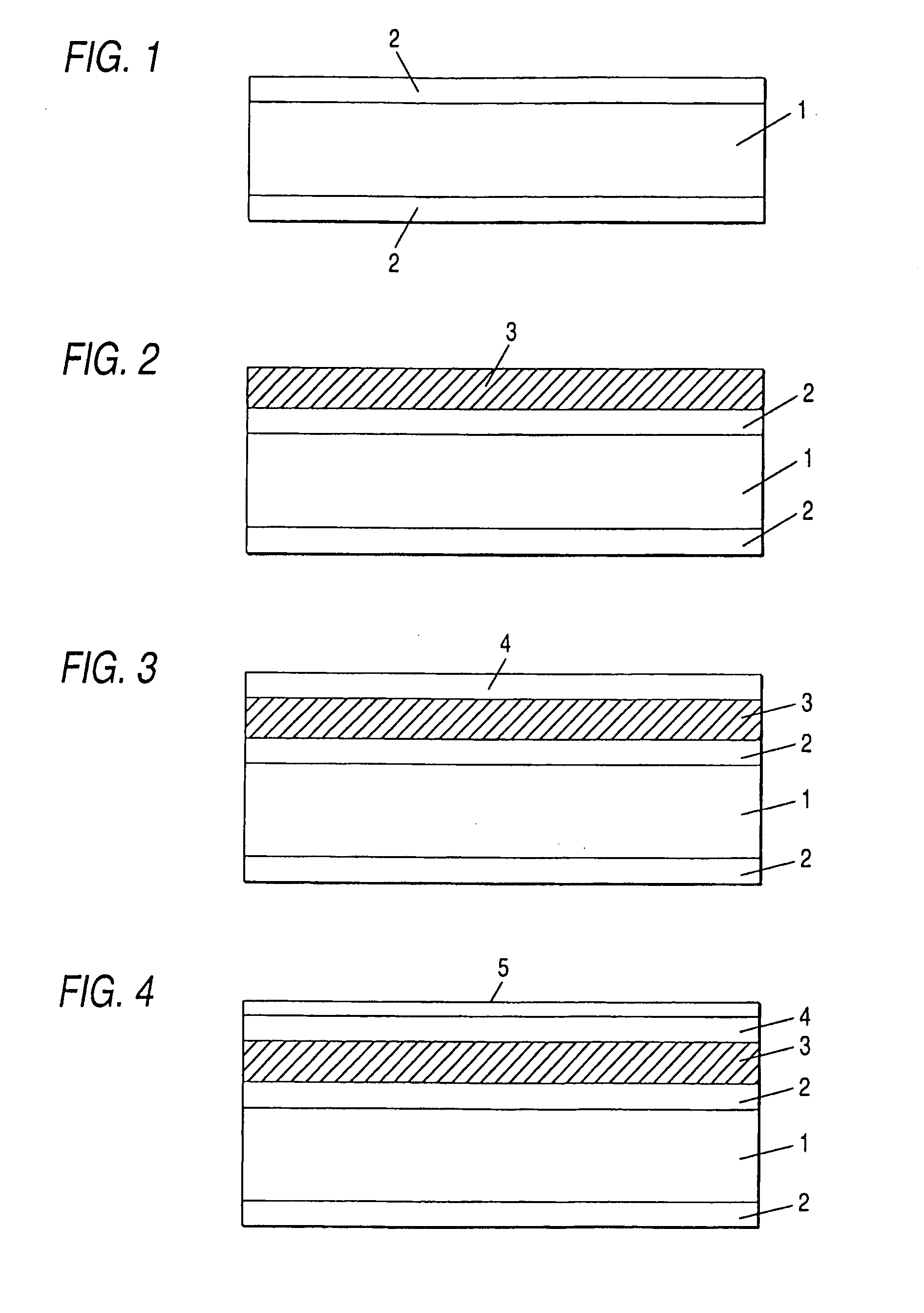
[0073] As shown in FIG. 1, a silicon substrate is used as a head base 1 for forming an ink chamber and 1 μm silicon thermal oxide films 2 are formed as diaphragms. In addition, a common electrode and silicon nitride, zirconium, zirconia, etc., can be used as diaphragms of the common electrode.

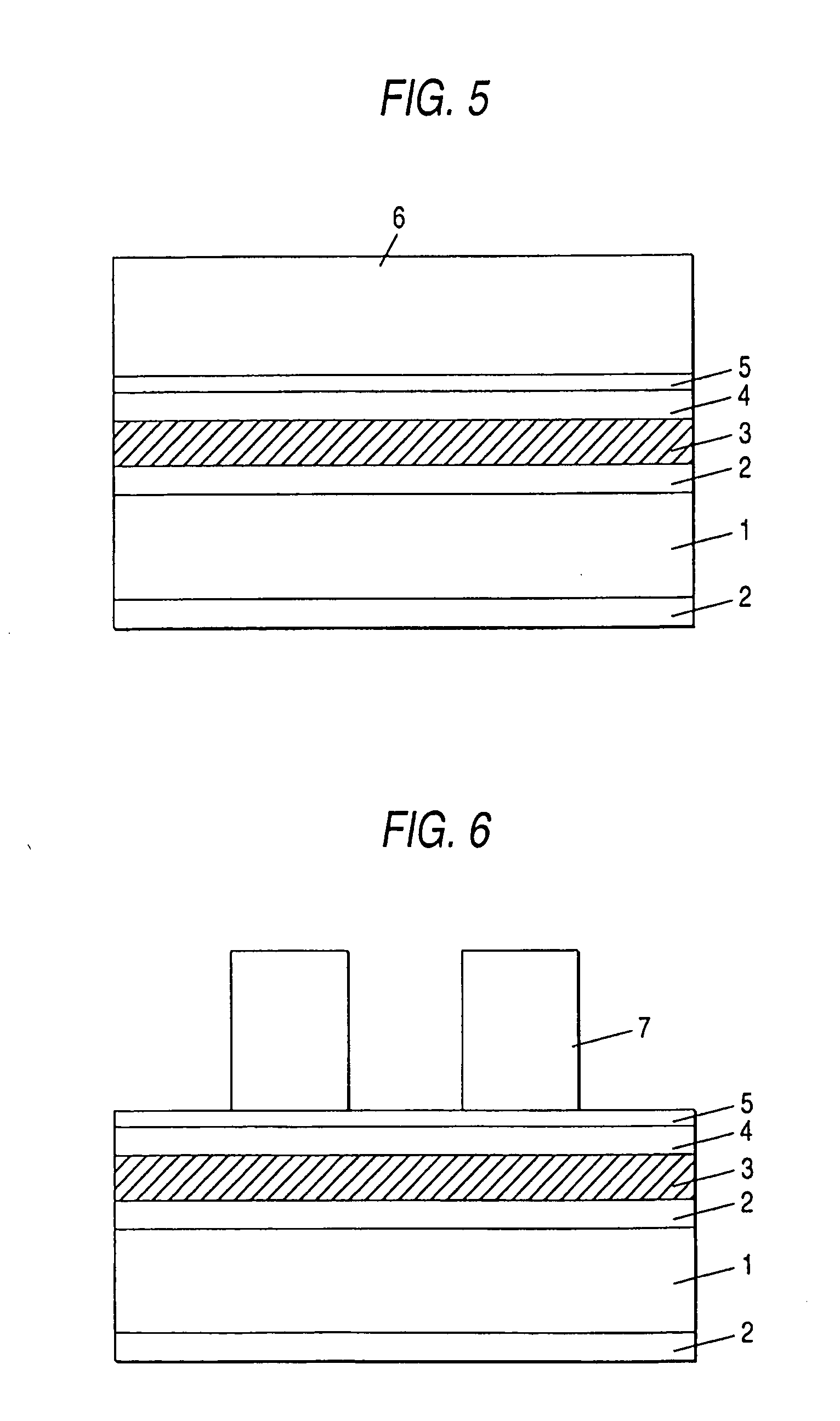
[0074] Next, a platinum film 0.8 μm thick is sputtered on the silicon thermal oxide film 2 as a common electrode 3 and a piezoelectric thin film 4 is formed on the common electrode 3, a platinum film 0.1 μm thick being sputtered on the piezoelectric thin film 4 as an upper electrode 5, as shown in FIGS. 2 to 4. In the embodiment, the silicon thermal oxide film 2 and the common electrode 3 function as a diaphragm. In addition, the upper electrode may be made of any material if the material is good in electr...


PUM

PropertyMeasurementUnit
thickaaaaaaaaaa
thicknessaaaaaaaaaa
thicknessaaaaaaaaaa

Abstract

An ink jet recording head comprising: a nozzle orifice for jetting ink; an ink chamber communicating with the nozzle; a diaphragm for pressurizing ink in the ink chamber; a piezoelectric thin film on the diaphragm; and an electrode for the piezoelectric thin film wherein the piezoelectric thin film and the electrode are patterned to the same shape.

Description

CROSS-REFERENCE TO RELATED APPLICATIONS [0001] This is a divisional of application Ser. No. 10 / 606,182 filed Jun. 26, 2003, which is a continuation of application Ser. No. 08 / 788,959 filed Jan. 24, 1997, now U.S. Pat. No. 6,609,785. The entire disclosures of the prior applications, application Ser. Nos. 10 / 606,182 and 08 / 788,959, are hereby incorporated by reference.BACKGROUND OF THE INVENTION [0002] This invention relates to an ink jet recording head using a piezoelectric thin film for an ink jet drive source and a manufacturing method therefor. Further, it relates to an ink jet recorder using the recording head. [0003] There is a piezoelectric ink jet recording head using PZT elements comprising PZT of piezoelectric elements as electromechanical transducer elements of liquid or ink jet drive source. This type of the piezoelectric ink jet recording head is proposed in, for example, Japanese Patent Application Laid-Open No. Hei 5-286131. [0004] This conventional head will be discuss...

Claims


Application Information

Patent Timeline
Patent Type & Authority Applications(United States)
IPC IPC(8): B41J2/045B41J2/055B41J2/14B41J2/16
CPCB41J2/14233B41J2/161B41J2/1623B41J2/1628B41J2/1629B41J2/1631Y10T29/49401B41J2/1645B41J2/1646B41J2002/14387Y10T29/42Y10T29/49155B41J2/1643
Inventor HASHIZUME, TSUTOMUTAKAHASHI, TETSUSHI
Owner SEIKO EPSON CORP
Learn More