Method of manufacturing projection objectives and set of projection objectives manufactured by that method

a technology of projection objectives and manufacturing methods, applied in the field of manufacturing projection objectives, can solve the problems of increasing the complexity of projection objectives, generating a new design of projection objectives, and still insufficient one or more results, and achieve high optical performance standards

Inactive Publication Date: 2007-01-18
CARL ZEISS SMT GMBH
View PDF6 Cites 28 Cited by
  • Summary
  • Abstract
  • Description
  • Claims
  • Application Information

AI Technical Summary

Benefits of technology

[0013] It is one object of the invention to provide a method of manufacturing projection objectives that allows to manufacture complex projection objectives for microlithography, in a cost effective way while maintaining high standards with respect to optical performance.

Problems solved by technology

As a consequence, increasingly high demands are placed on the complexity of the projection objective.
Generating a new design of a projection objective is a complicated task involving an optimization of structural parameters and quality parameters of the projection objective.
Typically, one or more results will still be insufficient with respect to a desired overall specification such that many efforts will have to be tried until a satisfactory solution is found.
Therefore, the costs of a new design in the phase of computational manufacturing may be high.
Typically, assembly of an optical system becomes more difficult with increasing complexity of the optical system in terms of components which have to be mounted together to obtain the complete optical system.
Also, it becomes more difficult to obtain a desired optical performance the more single mounting steps are involved in manufacturing an optical system, since typically each mounting step will introduce a certain amount of inaccuracy contributing to optical aberrations.

Method used


Image

  • Method of manufacturing projection objectives and set of projection objectives manufactured by that method
  • Method of manufacturing projection objectives and set of projection objectives manufactured by that method
  • Method of manufacturing projection objectives and set of projection objectives manufactured by that method

Examples


Embodiment Construction

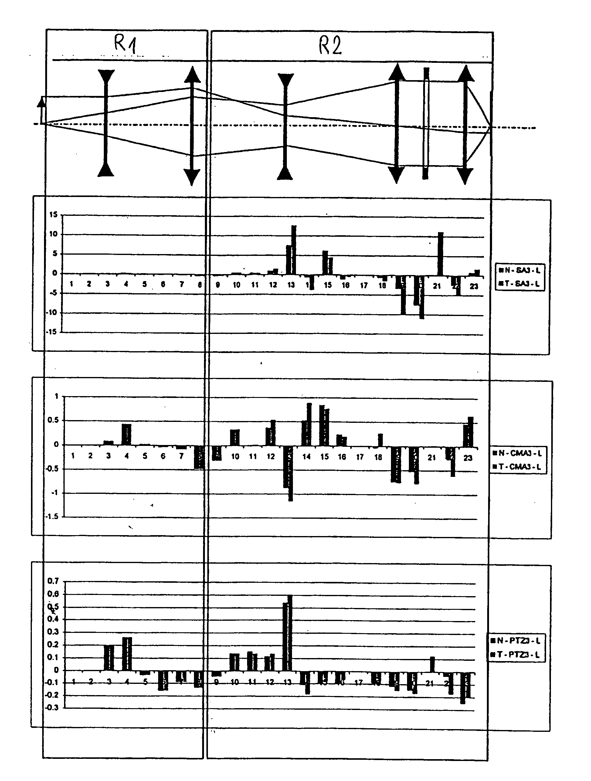
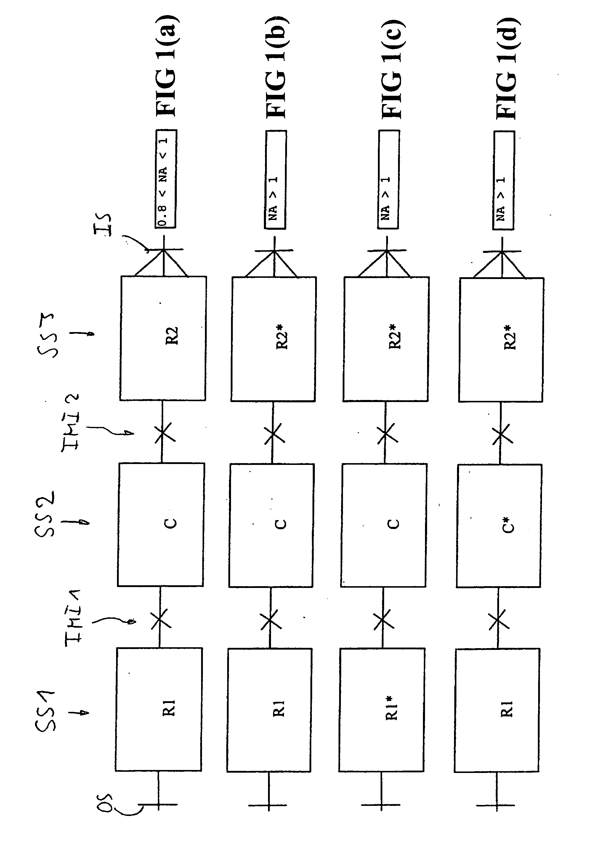
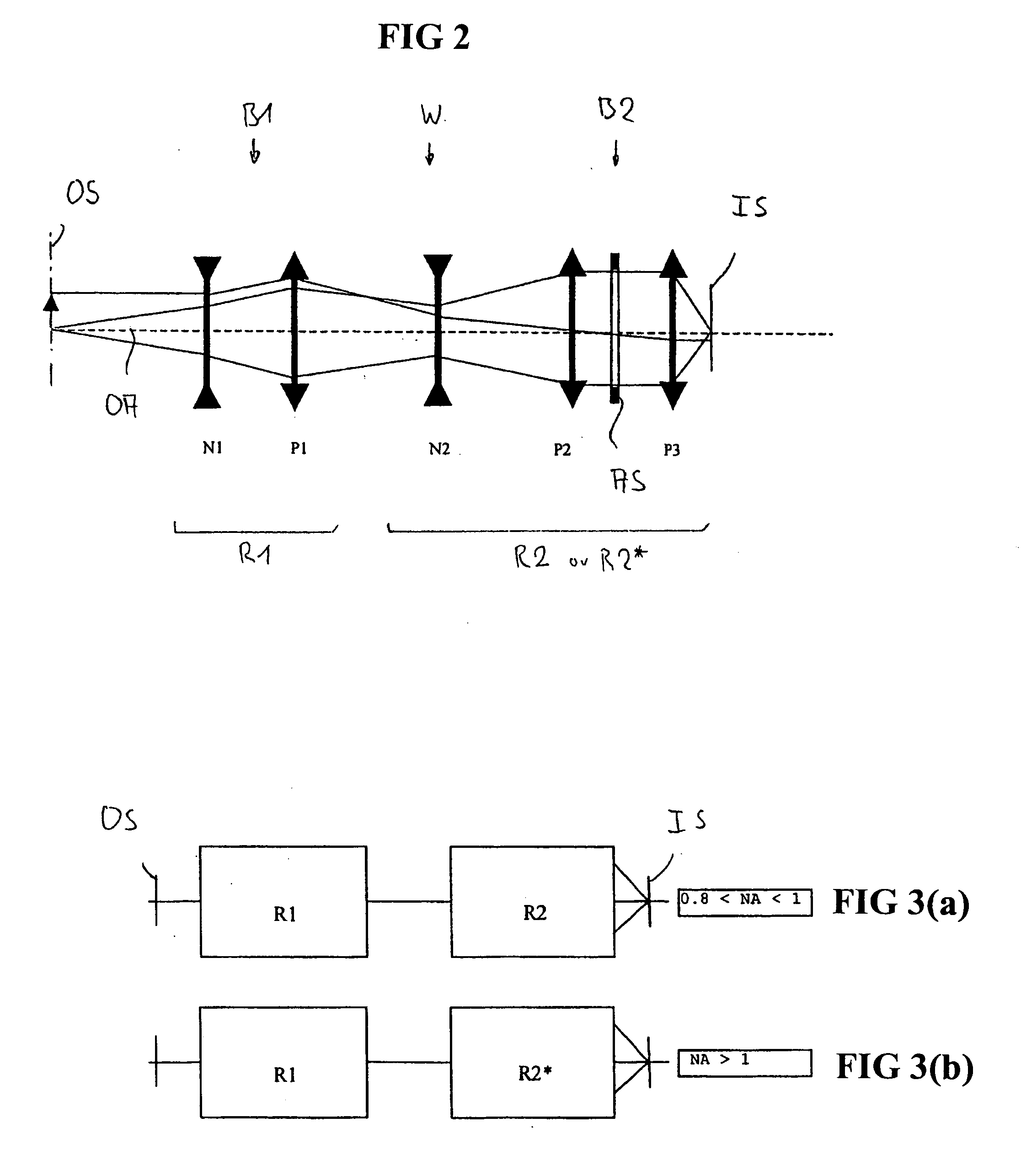
[0042] Some principles of the invention will now be explained with respect to FIG. 1, which shows schematic representations of related projection objectives of a set of projection objectives, where the projection objective is designed as a catadioptric projection objective for microlithography. The optical system is designed to project an image of a pattern on a reticle arranged in the planar object surface OS onto the planar image surface IS oriented parallel to the object surface on a reduced scale (e.g. 4:1) while creating exactly two real intermediate images IMI1, IMI2. The projection objective consists of three consecutive imaging subsystems SS1, SS2 and SS3 concatenated at the intermediate images and arranged in the sequence R-C-R, where “R” represents a refractive (dioptric) subsystem, “C” represents a catadioptric (or catoptric) subsystem and “-” represents the connection between the image subsystems at the intermediate image.

[0043] The first subsystem SS1 is a refractive (...


PUM


Abstract

In a method of manufacturing projection objectives including defining an initial design for a projection objective and optimizing the design using a merit function, a set of related projection objectives including a first projection objective and at least one second projection objective is defined. Further, a plurality of merit function components, each of which reflects a particular quality parameter, is defined. One of these merit function components defines a common module requirement requiring that the first projection objective and the second projection objective each include at least one common optical module that is constructed to be substantially identical for the first and the second projection objective. The method results in a set of projection objectives having at least one common optical module. Employing the method in the manufacturing of complex projection objectives, such as projection objectives for microlithography, facilitates the manufacturing process and allows substantial cost savings.

Description

[0001] This application claims benefit of provisional application U.S. Ser. No. 60 / 687,877 filed on Jun. 7, 2005. The complete disclosure of this provisional application is incorporated into the present application by reference.BACKGROUND OF THE INVENTION [0002] 1. Field of the invention [0003] The present invention relates to a method of manufacturing projection objectives including defining an initial design for a projection objective and optimizing the design using a merit function. The method is used in the manufacturing of projection objectives, for example those used in a microlithographic process of manufacturing miniaturized devices. [0004] 2. Brief Description of the Related Art [0005] Microlithographic processes are commonly used in the manufacture of miniaturized devices, such as integrated circuits, liquid crystal elements, micro-patterned structures and micro-mechanical components. In that process, a projection objective serves to project patterns of a patterning struct...

Claims


Application Information

Patent Timeline
Patent Type & Authority Applications(United States)
IPC IPC(8): G03B21/00
CPCG03B21/00G03F7/70225G02B27/0012G03F7/70241G03F7/705G03F7/70233G03B21/006
Inventor DODOC, AURELIANULRICH, WILHELMFELDMANN, HEIKO
Owner CARL ZEISS SMT GMBH
Why Eureka
Try Eureka