Compression design for high energy short pulse fiber laser

a compression design and fiber laser technology, applied in the direction of laser details, basic electric elements, optical resonator shape and construction, etc., can solve the problems of limited cpa systems, limited cpa systems, and limitations that were not addressed in conventional technologies, so as to achieve flexible modulation and a higher degree of flexibility of dispersion compensation

Active Publication Date: 2007-01-18
POLARONYX
View PDF5 Cites 29 Cited by
  • Summary
  • Abstract
  • Description
  • Claims
  • Application Information

AI Technical Summary

Benefits of technology

[0006] It is another aspect of this invention that in order to further compensate a higher dispersion, a compensator is implemented in a fiber laser system that includes a pair of grating lenses and a pair of prisms as a combined compensator to compensate a higher order dispersion including the TOD such that a high quality, compact and reliable fiber laser system can be provided.
[0008] It is a further aspect of this invention that the higher order dispersions are compensated with a compensator that comprises a deformable mirror that can be flexibly modulated by a controller implemented with compensation algorithms. A combined compensator implemented with a grating lens with the deformable mirror can provide higher degree of flexibility of dispersion compensations.

Problems solved by technology

Even though current technologies of fiber laser have made significant progress toward achieving a compact and reliable fiber laser system providing high quality output laser with ever increasing output energy, however those of ordinary skill in the art are still confronted with technical limitations and difficulties.
Specifically, in a fiber laser system implemented with the Chirped Pulse Amplification (CPA) for short pulse high power laser amplifier, the CPA systems are still limited by the technical difficulties that the third order dispersion (TOD) limits the scalability of the laser systems.
Such limitations were not addressed in the conventional technologies due to the fact that the conventional solid-state laser utilizes Grating-Lens combination and Treacy compressor for pulse stretching and compressing.
Ideally, in such solid-state systems, all orders of dispersion can be compensated, but the material dispersion can distort and damage this ideal situation.
However, for a fiber laser system, the situation is different due to the fact that in the fiber laser systems, attempts are made by using the fiber stretcher to replace the grating-lens combination for the purpose of significantly increasing the system reliability.
However, the TOD limits the ability for de-chirping when using Treacy compressor since both fiber stretcher and Treacy compressor have positive TOD even this combination can remove the second order dispersion completely.
This issue of TOD dispersion makes it more difficult to develop a high-energy fiber laser amplifier with <200 fs pulse width.
Actually, the technical difficulty of TOD dispersion is even more pronounced for laser system of higher energy.
Therefore, for laser system of higher energy, it is even more difficult to re-compress the pulse to the original pulse width.

Method used


Image

  • Compression design for high energy short pulse fiber laser
  • Compression design for high energy short pulse fiber laser
  • Compression design for high energy short pulse fiber laser

Examples


Embodiment Construction

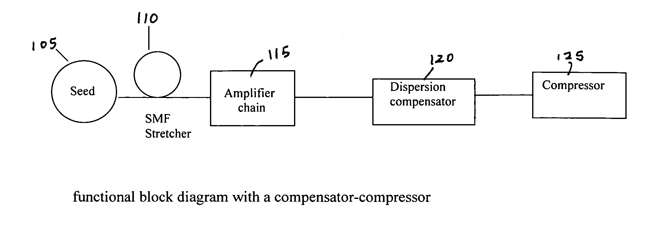
[0017] Referring to FIG. 1 for a schematic diagram of a fiber laser system 100 of this invention that implements a dispersion compensator of this invention. The laser system 100 includes a laser seed 105 for generating a seed laser for projecting into a laser stretcher 110 to stretch the laser pulse. The stretcher 110 generates laser pulse with stretched pulse width is projected into a series of laser amplifiers 115 to amplify the laser into higher energy. The amplified laser is then projected into a TOD compensator 120 of this invention to compensate the dispersions generated due to the TOD effects. The amplified and TOD compensated laser outputted from the dispersion compressor 120 are then projected to a pulse compressor 125 to re-compress the pulse width of the laser to output a laser with original pulse width.

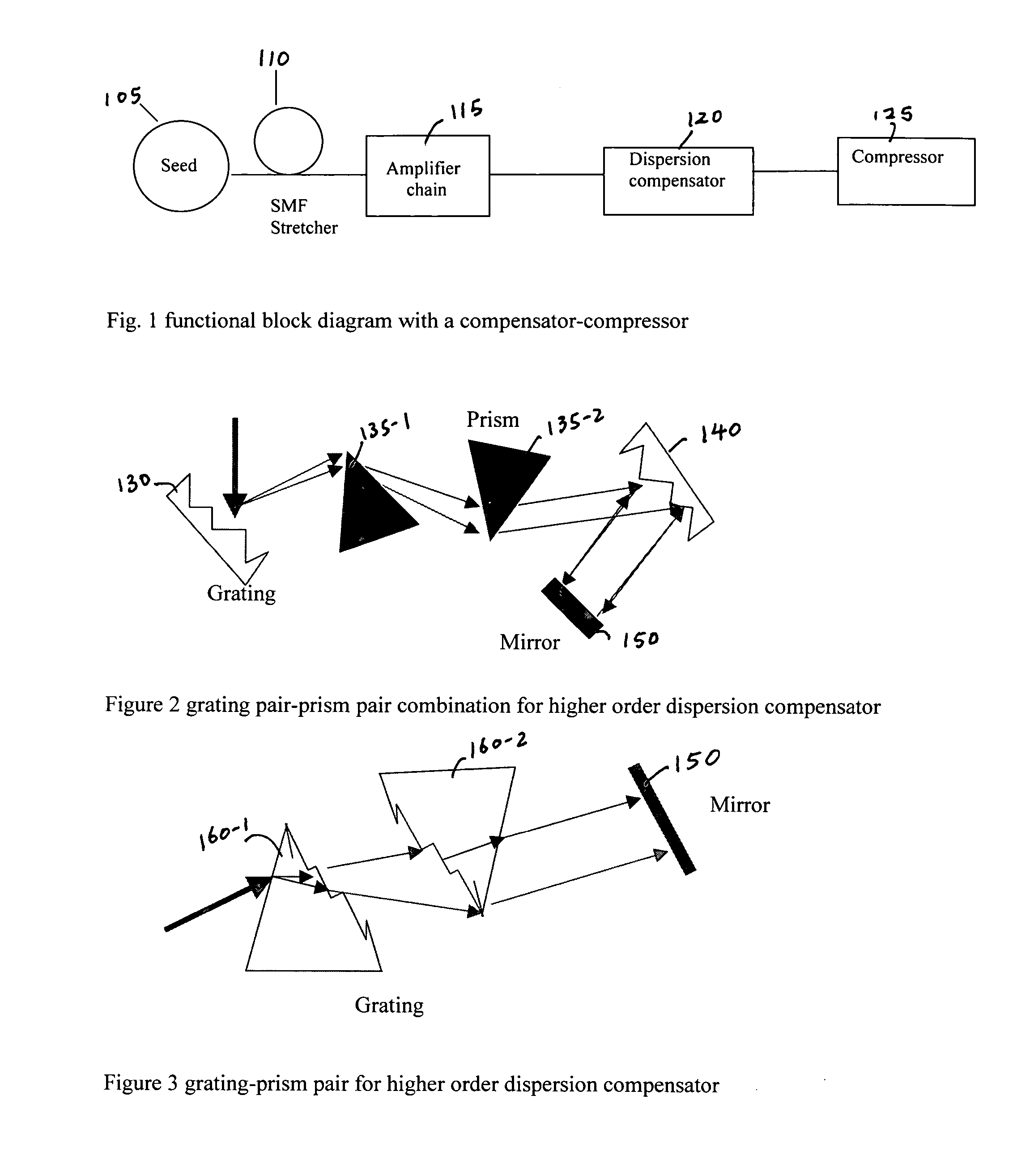
[0018] The device of a TOD compensator 120 shown in FIG. 1 can be implemented in many configurations. Referring to FIG. 2 for a first embodiment that includes a configura...


PUM


Abstract

A fiber Chirped Pulse Amplification (CPA) laser system includes a fiber mode-locking oscillator for generating a laser for projecting to a fiber stretcher for stretching a pulse width of the laser. The fiber CPA laser system further includes a multistage amplifier for amplifying the laser and a high-order dispersion compensating compressor for compensating high order dispersions and compressing the pulse width of the laser. The high-order dispersion compensating compressor further includes a pair of gratings coupled with a pair of prisms, a grating pair engraved on the surfaces of a pair of prisms, a chirped grating pair and a phase modulator consists of a grating and a deformable mirror, for generating a negative group velocity dispersion (GVD) and a negative third order dispersion (TOD) for the laser.

Description

[0001] This Formal Application claims a Priority Date of Jun. 30, 2005 benefit from two Provisional Patent Applications 60 / 696,372 and Jul. 1, 2005 benefit from another Provisional Patent Application 60 / 696,275 filed by the same Applicant of this Application. The disclosures made in 60 / 696,372 and 60 / 696,275 are hereby incorporated by reference in this Patent Application.FIELD OF THE INVENTION [0002] The present invention relates generally to apparatuses and methods for providing fiber laser system. More particularly, this invention relates a design for dispersion compensation in Chirped Pulse Amplification (CPA) fiber laser system. BACKGROUND OF THE INVENTION [0003] Even though current technologies of fiber laser have made significant progress toward achieving a compact and reliable fiber laser system providing high quality output laser with ever increasing output energy, however those of ordinary skill in the art are still confronted with technical limitations and difficulties. Sp...

Claims


Application Information

Patent Timeline
Patent Type & Authority Applications(United States)
IPC IPC(8): H01S3/30H01S3/098H01S3/10H01S3/08
CPCH01S3/06725H01S3/0057
Inventor LIU, JIANXIA, JIANGFAN
Owner POLARONYX
Why Eureka
Try Eureka