Vertical cavity surface emitting laser

a laser and vertical cavity technology, applied in the direction of laser details, semiconductor lasers, electrical devices, etc., can solve the problems of difficult to manufacture such a special substrate, polarization direction may not be stabilized in one direction, and the price of gradient substrates is greatly increased. , to achieve the effect of easy and inexpensive manufacturing, and easy and inexpensive manufacturing

Active Publication Date: 2007-01-18
SONY CORP
View PDF8 Cites 131 Cited by
  • Summary
  • Abstract
  • Description
  • Claims
  • Application Information

AI Technical Summary

Benefits of technology

[0024] According to the VCSEL of the embodiment of the invention, the light emitting window is provided in the region corresponding to one diagonal line of the current injection region, and the pair of grooves is provided with the light emitting window in between. Therefore, the polarization direction of laser light can be stabilized in one direction. Further, since there is no need to use a special substrate, the VCSEL can be easily and inexpensively manufactured.
[0025] Further, since reflectance of the peripheral region, which is a region of the light emitting window other than the central region, is re...

Problems solved by technology

Therefore, the gradient substrate is greatly expensive compared to standard substrates such as a face (001) substrate.
Therefore, it is difficult to manufacture such a special substrate.
However, the polarization direction may not be stabilized in one direction unless the distance of the short side of the resonance region is reduced down to the degree at which diffraction loss ...

Method used


Image

  • Vertical cavity surface emitting laser
  • Vertical cavity surface emitting laser
  • Vertical cavity surface emitting laser

Examples


first embodiment

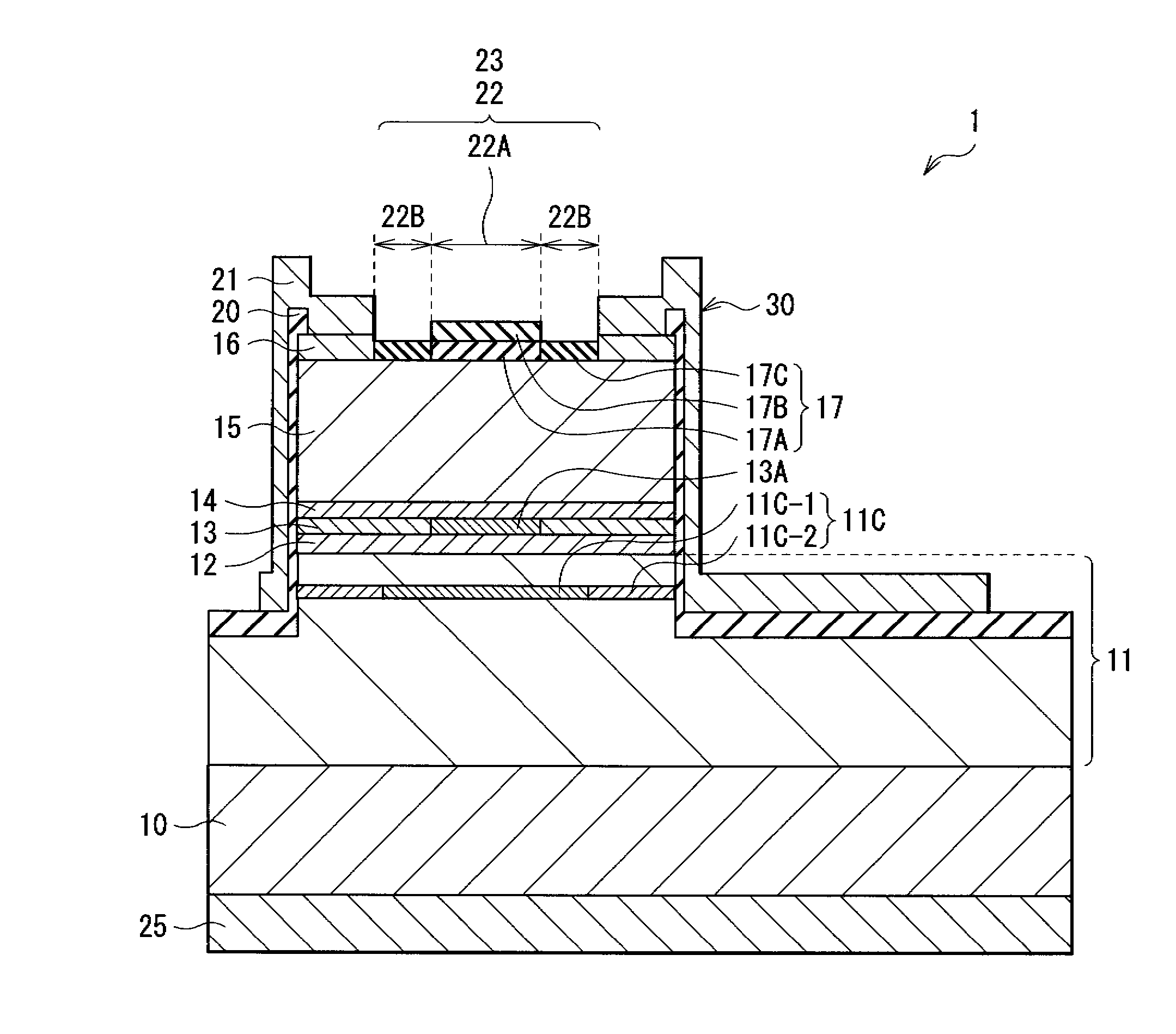
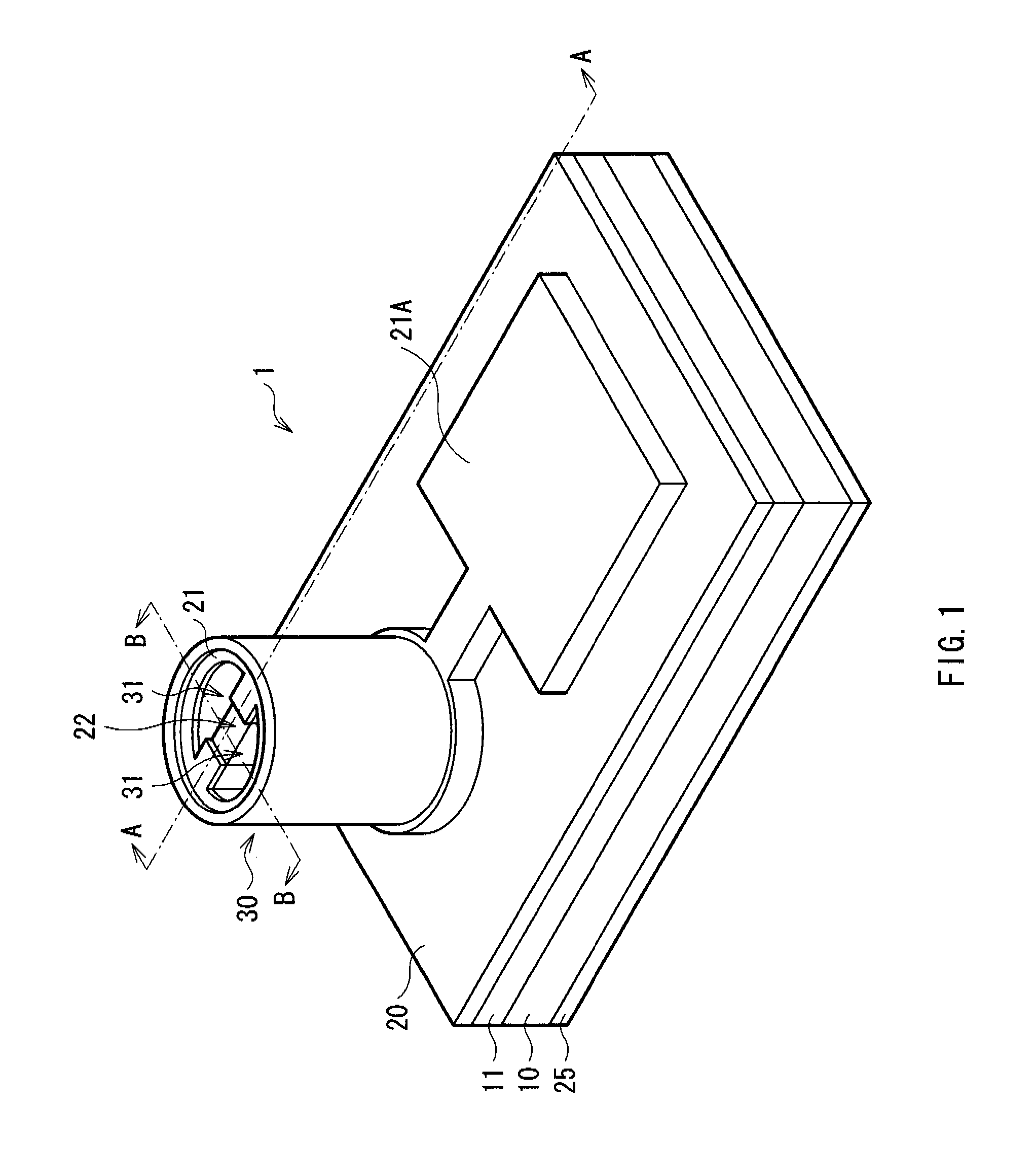
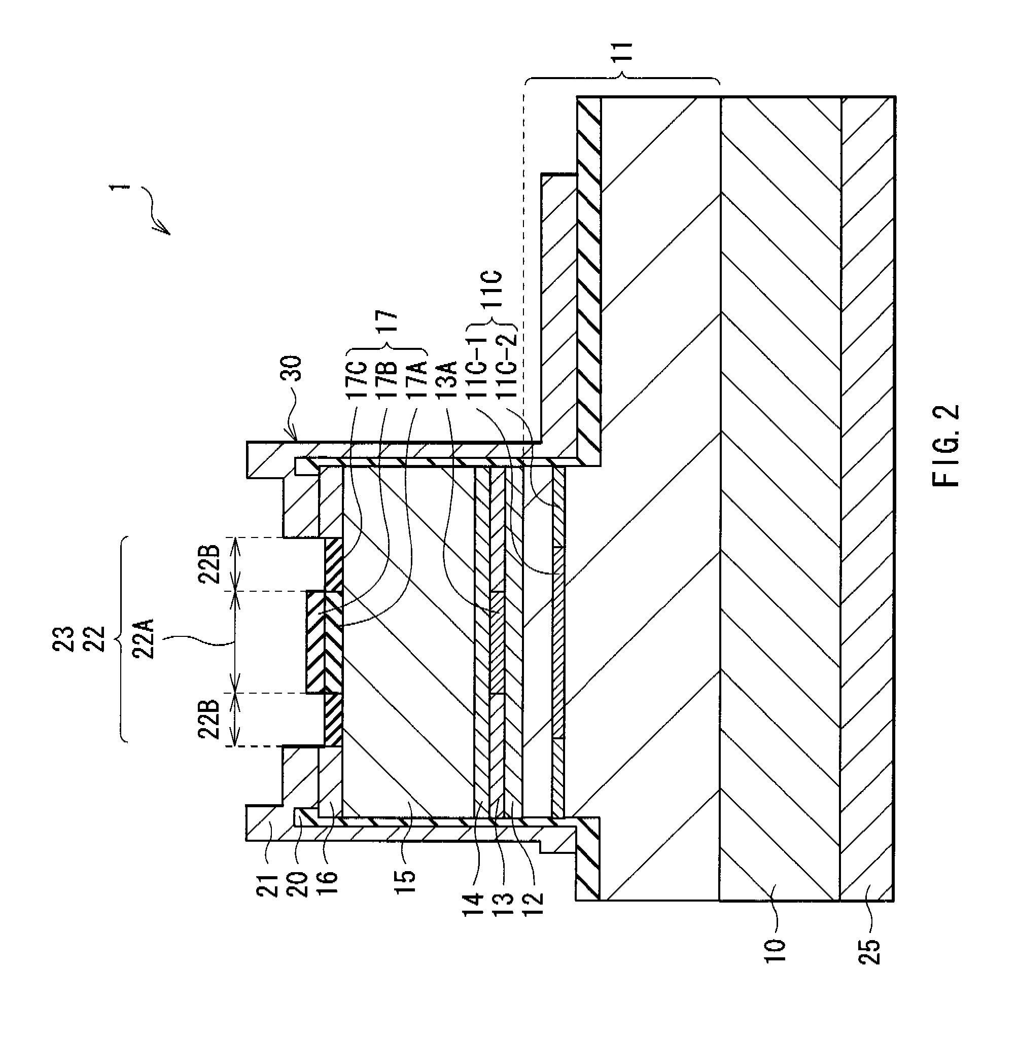
[0047]FIG. 1 shows a perspective view of a VCSEL 1 according to an embodiment of the invention. FIG. 2 shows a cross sectional structure taken along arrows A-A of the VCSEL 1 of FIG. 1. FIG. 3 shows a cross sectional structure taken along arrows B-B of the VCSEL 1 of FIG. 1. FIG. 4 shows a top face structure of a mesa portion 30 of FIG. 1. FIG. 5 shows a cross sectional structure of a current confinement layer 11C of FIG. 2. FIG. 6A shows a cross sectional structure of a transverse mode adjustment layer 17 and the vicinity thereof. FIG. 6B shows a reflectance distribution of the transverse mode adjustment layer 17 of FIG. 2.

[0048] The VCSEL 1 has a laser structure portion in which a lower DBR mirror layer 11 (first multilayer film reflector), a lower cladding layer 12, an active layer 13, an upper cladding layer 14, an upper DBR mirror layer 15 (second multilayer film reflector), a p-side contact layer 16, and the transverse mode adjustment layer 17 are layered in this order on one...

second embodiment

[0093]FIGS. 10A and 10B respectively show a structure of a transverse mode adjustment layer 27 and the vicinity thereof of a VCSEL 2 according to a second embodiment, and a reflectance distribution of the transverse mode adjustment layer 27. The VCSEL 2 differs from the foregoing embodiment in that only the reflectance of the peripheral region 22B is lowered than that of the central region 22A by the transverse mode adjustment layer 27 composed of a forth adjustment layer 27A provided in the central region 22A of the light emitting window 22 and a fifth adjustment layer 27B provided in the peripheral region 22B thereof. Descriptions will be given of the fourth adjustment layer 27A and the fifth adjustment layer 27B. In FIGS. 10A and 10B, the case that the transverse mode adjustment layer 27 is convex is shown. However, the shape of the transverse mode adjustment layer 27 may be concave depending on the magnitude relation of thickness between the forth adjustment layer 27A and the fi...

third embodiment

[0098]FIGS. 11A and 11B respectively show a structure of a transverse mode adjustment layer 47 and the vicinity thereof of a VCSEL 4 according to a third embodiment, and a reflectance distribution of the transverse mode adjustment layer 47. The VCSEL 4 differs from the foregoing embodiments in that only reflectance of the peripheral region 22B is lowered than that of the central region 22A by the transverse mode adjustment layer 47 composed of a tenth adjustment layer 47A and an eleventh adjustment layer 47B provided in the central region 22A of the light emitting window 22 and a twelfth adjustment layer 47C and the thirteenth adjustment layer 47D provided in the peripheral region 22B thereof. Descriptions will be given of these adjustment layers 47A, 47B, 47C, and 47D. In FIGS. 11A and 11B, the case that the transverse mode adjustment layer 47 is convex is shown. However, the shape of the transverse mode adjustment layer 47 may be concave depending on the magnitude relation of thic...


PUM


Abstract

In a VCSEL, a first multilayer film reflector, an active layer having a light emitting central region, a second multilayer film reflector, and a transverse mode adjustment layer are layered in this order. The first multilayer film reflector has a quadrangle current injection region with an intersection of diagonal lines corresponding to the light emitting central region. The second multilayer film reflector has a light emitting window provided in a region corresponding to one diagonal line of the current injection region and a pair of grooves provided with the light emitting window in between. The transverse mode adjustment layer is provided correspondingly to the light emitting window, and reflectance of a peripheral region thereof is lower than that of a central region thereof.

Description

CROSS REFERENCES TO RELATED APPLICATIONS [0001] The present invention contains subject matter related to Japanese Patent Application JP 2005-195090 filed in the Japanese Patent Office on Jul. 4, 2005, Japanese Patent Application JP 2005-372099 filed in the Japanese Patent Office on Dec. 26, 2005, and Japanese Patent Application JP 2006-159719 filed in the Japanese Patent Office on Jun. 8, 2006, the entire contents of which being incorporated herein by references. BACKGROUND OF THE INVENTION [0002] 1. Field of the Invention [0003] The present invention relates to a vertical cavity surface emitting laser (VCSEL) which has a laser light emitting region on the top face, particularly to a VCSEL which can be suitably applied to purposes necessitating light output of the low-order transverse mode. [0004] 2. Description of the Related Art [0005] A VCSEL emits light in the direction perpendicular to a substrate differently from the existing edge-emitting laser diodes. In the VCSEL, many devi...

Claims


Application Information

Patent Timeline
IPC IPC(8): H01S3/098H01S5/00
CPCH01S5/18313H01S5/18325H01S5/18327H01S2301/166H01S5/18344H01S5/18355H01S5/18391H01S5/18338
Inventor MAEDA, OSAMUSHIOZAKI, MASAKIYAMAGUCHI, NORIHIKOYAMAUCHI, YOSHINORIMASUI, YUJI
Owner SONY CORP
Why Eureka
Try Eureka