Method and apparatus for transferring multiple toner images and image forming apparatus

a technology of toner image and forming apparatus, which is applied in the direction of electrographic process apparatus, printing, instruments, etc., can solve the problems of changing the optical characteristics of the resin, the misalignment of toner images, and the expansion and contraction of the latent image carrier, so as to reduce the misalignment

Inactive Publication Date: 2007-01-18
RICOH KK
View PDF7 Cites 44 Cited by
  • Summary
  • Abstract
  • Description
  • Claims
  • Application Information

AI Technical Summary

Benefits of technology

[0017] An image forming apparatus according to still another aspect of the present invention, which forms a multicolor image or a color image, includes an apparatus for transferring a plurality of toner images formed on a plurality of image carriers of different colors onto a sheet-type recording medium. The apparatus includes a detecting unit that detects optically a mark image for adjusting a transfer position that is optically formed on each of the image carriers, visualized as a toner image, and transferred to a common transfer medium; a control-amount creating unit that creates a control amount to control linear velocities of the image carriers based on a mutual positional relationship between the mark images detected; and a controlling unit that controls rotational drives of the image carriers based on the control amount created. The control-amount creating unit creates the control amount that reduces a misalignment between the toner images transferred.

Problems solved by technology

Moreover, even if it is presumed that the misalignment could be eliminated by adjusting the apparatus perfectly, change in optical characteristics of a resin lens due to a change in temperature, and an expansion and contraction of the latent image carrier etc. is inevitable, and the misalignment of the toner images occurs due to these factors.
However, since the rotation of the rotating polygon mirror being extremely high-speed rotation, it is not easy to control the phase of rotation and necessitates an expensive controlling unit, thereby leading to a rise in cost.
However, in this case, it is not possible to control by corresponding the phase of rotation of the rotating polygon mirror with each latent image carrier and an effect of decreasing the registration has limitations.

Method used


Image

  • Method and apparatus for transferring multiple toner images and image forming apparatus
  • Method and apparatus for transferring multiple toner images and image forming apparatus
  • Method and apparatus for transferring multiple toner images and image forming apparatus

Examples


first embodiment

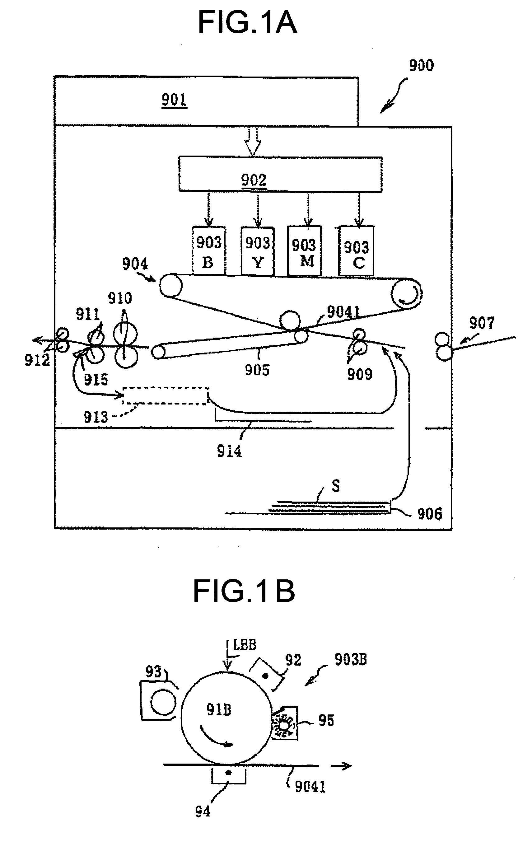
[0025]FIGS. 1A and 1B are schematics of an image forming apparatus according to the present invention. An image forming apparatus 900 shown in FIG. 1A is a tandem color-image forming apparatus. A color document is read in a reading section 901 by color separation into red, green, and blue colors, and based on this information read, and image data corresponding to each of black (B), yellow (Y), magenta (M), and cyan (C) colors is created.

[0026] This color data is provided for optical writing in imaging stations 903B, 903Y, 903M, and 903C by an optical writing unit 902. Since the imaging stations 903B, 903Y, 903M, and 903C have an identical structure, description is made with an example of the imaging station 903B.

[0027] The imaging station 903B includes a photosensitive drum 91B as a latent image carrier that is driven and rotated in a counterclockwise direction, and a charging charger 92, a developing unit 93, a transfer charger 94, and a cleaning unit 95 that are disposed around t...

second embodiment

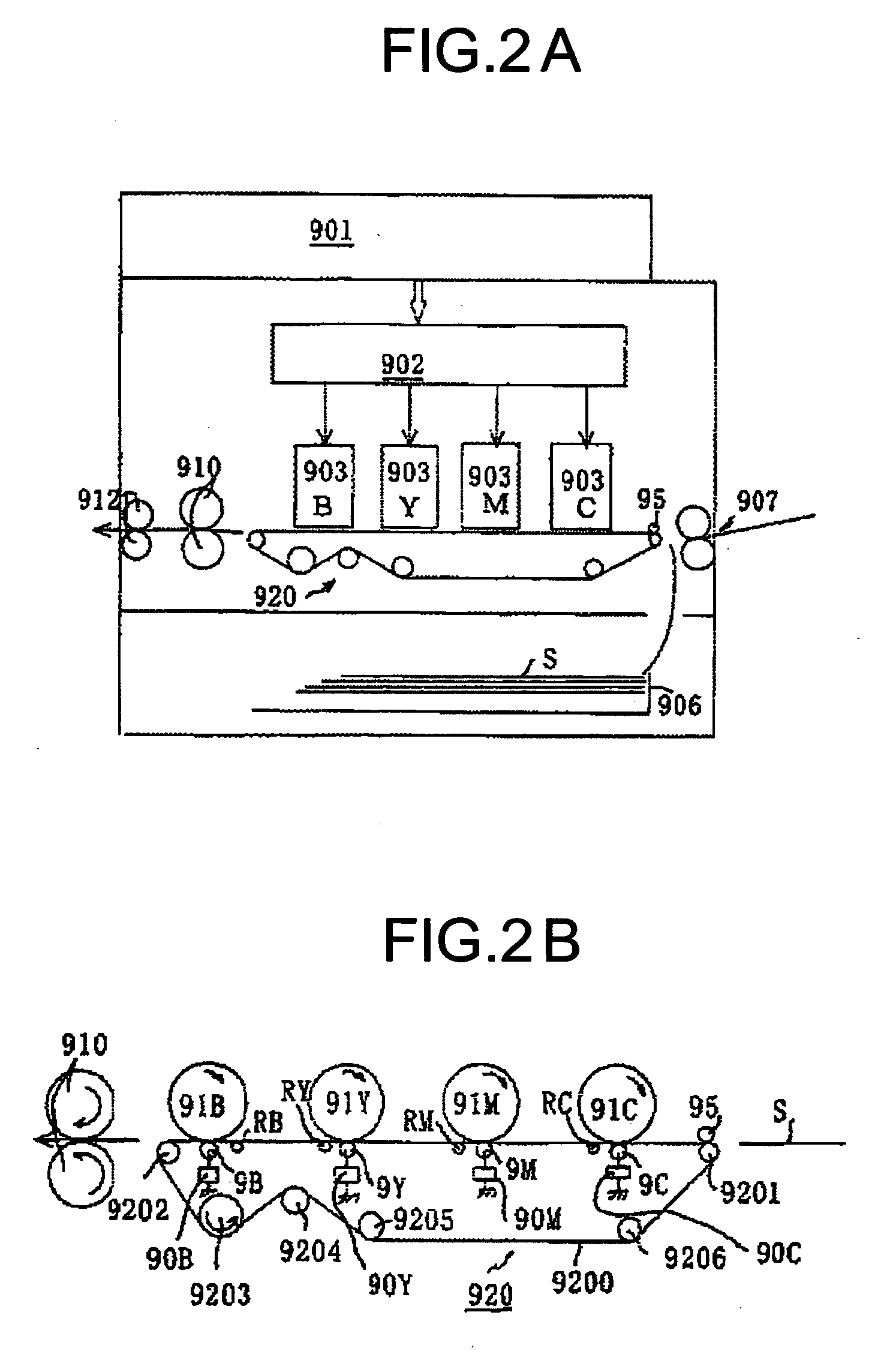
[0034]FIGS. 2A and 2B are schematics of an image forming apparatus according to the present invention. For the sake of explanation, same reference numerals are used as in FIGS. 1A and 1B for components for which there is no possibility of confusion. For the reference numerals identical with those in FIGS. 1A and 1B, the description mentioned above conforming to FIGS. 1A and 1B is to be referred to.

[0035] An image forming apparatus shown in FIG. 2A as well, is a tandem color-image forming apparatus. A color document is read in the reading section 901 by color separation into red, green, and blue colors, and based on this information read, and image data corresponding to each of B, Y, M, and C colors is created. This color data is provided for optical writing in the imaging stations 903B, 903Y, 903M, and 903C by the optical writing unit 902.

[0036]FIG. 2B is an illustration of structurally important components of a transfer unit 920. As shown in the diagram, an upper surface of a shee...

third embodiment

[0044]FIGS. 3A, 3B, and 3C are schematics for illustrating an apparatus for transferring multiple-toners according to the present invention.

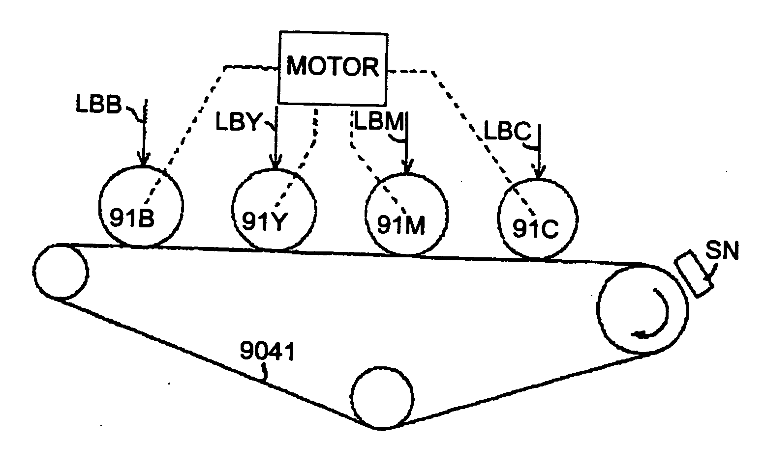
[0045] According to the third embodiment, the four photosensitive drums 91B, 91Y, 91M, and 91C are driven by a common motor and a gear mechanism that is not shown in the diagram so that the mutual linear velocity of peripheral surfaces is equal.

[0046] For registration, as shown in FIG. 3B, mark images PTY, PTC, PTM, and PTB for adjustment of transfer position are formed as toner images (by optical writing and developing) on each of the image carriers 91Y, 91C, 91M, and 91B. These mark images PTY, PTC, PTM, and PTB are transferred to the intermediate transfer belt 9041, which is a common transfer medium, and a mutual positional relationship of the mark images is read and detected optically by a detecting unit SN.

[0047] In the mark images PTY, PTC, PTM, and PTB in FIG. 3B, each dashed line mark indicates an ideal position with no shift in the re...


PUM


Abstract

A method of transferring a plurality of toner images formed on a plurality of image carriers of different colors onto a sheet-type recording medium includes forming a mark image for adjusting a transfer position on each of the image carriers as a toner image; transferring the mark images to a common transfer medium; detecting optically a mutual positional relationship between the mark images; and controlling linear velocities of the image carriers based on a result of detecting the mutual positional relationship between the mark images, to transfer the toner images onto the sheet-type recording medium with a reduced misalignment between the toner images.

Description

CROSS-REFERENCE TO RELATED APPLICATIONS [0001] The present document incorporates by reference the entire contents of Japanese application number, 2002-365455 filed in Japan on Dec. 17, 2002. BACKGROUND OF THE INVENTION [0002] 1. Field of the Invention [0003] The present invention relates to a method and an apparatus for transferring multiple toner images and an image forming apparatus. [0004] 2. Description of the Related Art [0005] Image forming apparatus that uses an optical writing, in which a principle of electrophotography is used, has been known so far as a digital copier, an optical printer, an optical plotter, and a facsimile apparatus etc. In these image forming apparatuses, colorization of an image formed has been advancing and there has been a strong demand for speeding up the image formation. Realization of a so called tandem image forming apparatus that enables color image formation at a speed similar to that of monochrome image formation has been intended. [0006] In th...

Claims


Application Information

Patent Timeline
Patent Type & Authority Applications(United States)
IPC IPC(8): G03G15/01
CPCG03G2215/0119G03G2215/0129G03G15/0194G03G2215/0161G03G2215/0141
Inventor KAWAGOE, KATSUYA
Owner RICOH KK
Why Eureka
Try Eureka