Blade for wind turbine

Inactive Publication Date: 2007-01-18
PARERA JORGE
View PDF4 Cites 24 Cited by
  • Summary
  • Abstract
  • Description
  • Claims
  • Application Information

AI Technical Summary

Benefits of technology

[0013] The present invention is directed to an improved design of the blade used in a wind turbine electrical generator. In this design the speed and/or the pressure of the air in the hollow interior of the blade is increased such that when the air is released through openings in the blade wall from the blade interior, it creates an increased thrust to the blade causing it to rotate at a greater speed, thereby producing more electrical energy in a more efficient manner. In one embodiment of the invention, the velocity of the air within the blade interior is increased by the provision of a fan or vacuum at an air inlet. The air at an increased v

Problems solved by technology

Particularly within the past decade or so, it is becoming increasingly clear that alternatives to fossil fuels to generate electricity are needed and that this need is becoming more critical with each passing year.
The pollution caused by the burning of fossil fuels to generate electricity has already created significant destruction to the environment resulting in global warming, which if not stopped or reduced significantly, could well lead to disastrous declines in the quality of life of billions of people around the world.
The supply of fossil fuels is constantly being depleted, and as the demand for electricity continues to surge dramatically in countries such as China, the cost of fossil fuels will continue to rise and the supply of fossil fuels will become more scarce.
Although it has clear advantages over fossil fuel, such as its unlimited supply and freedom from pollutants, the use of wind

Method used


Image

  • Blade for wind turbine
  • Blade for wind turbine
  • Blade for wind turbine

Examples


Embodiment Construction

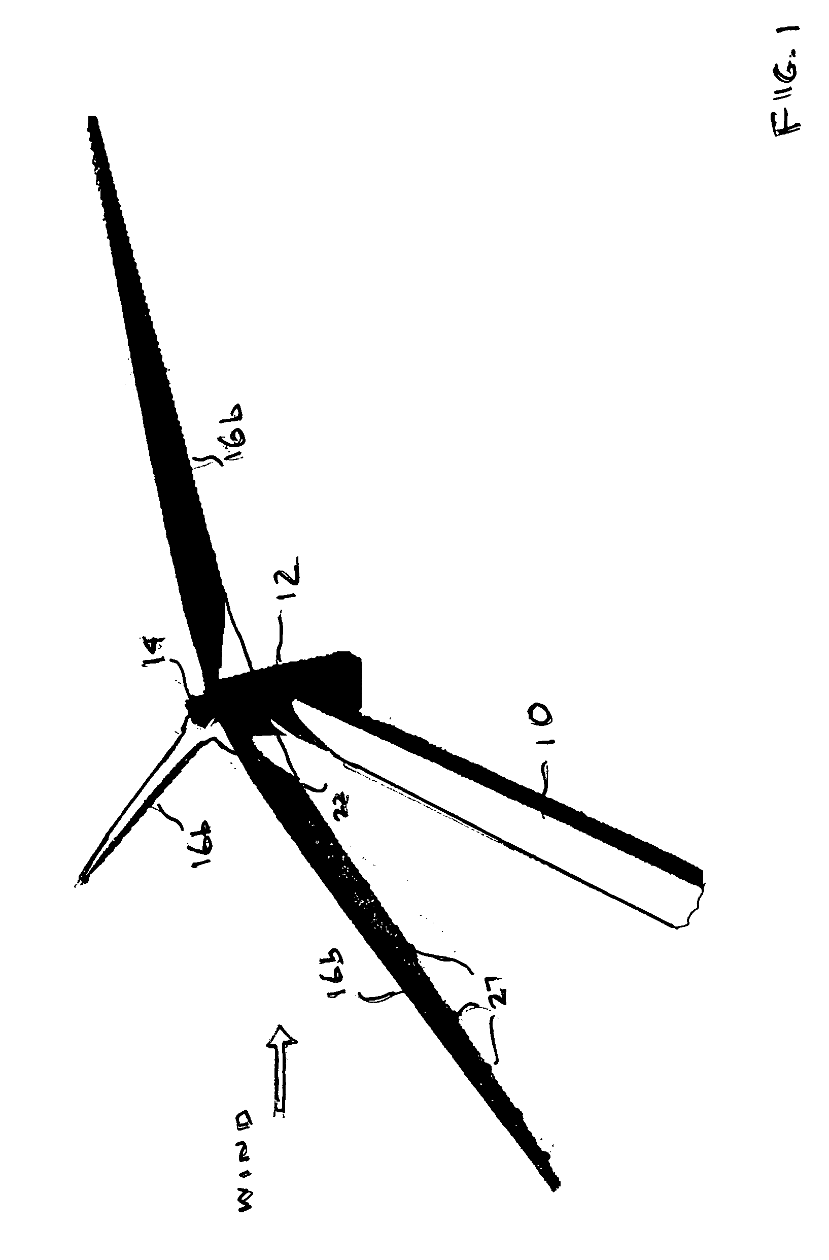
[0021] Referring to the drawings, there is shown in FIG. 1 a wind turbine supported on a tower 10. Mounted on top of the tower is a nacelle 12, which houses, as is conventional, a generator (not shown) whose rotor (also not shown) is bearing mounted to the nacelle. A blade hub 14 is secured to the free end of the rotor and three equiangularly spaced turbine blades 16 are secured at their lower ends to the blade hub 14. The blades 16 in FIG. 1 are, for purposes of illustration, of the configuration described below with respect to the embodiment of the invention illustrated in FIG. 3. As is conventional, the blades 16 are in the shape of an airfoil so that as the ambient wind passes over the blade surface, the blades are caused to rotate and to cause the rotor to rotate in the generator so as to generate electricity, also in a conventional manner. In accordance with the present invention, the turbine blades 16 are designed to produce a greater amount of electricity for a given ambient...


PUM


Abstract

A blade for a wind turbine includes a means for causing air at an increased velocity and/or pressure to escape from exit openings in the blade, thereby to apply a force that increases the rotational velocity of the blade. In one embodiment of the invention described a fan or vacuum in the blade causes an increase in the air velocity within a hollow air chamber in the blade. In another embodiment of the invention described, a compressor or one-way valve is used to increase the pressure of the air within the interior hollow air chamber. Pressure and diameter adjustable valves may be provided at each exit opening or orifice to allow the air to exit from the blade only when the air pressure within the blade exceeds a preset level. Also disclosed is the provision of valves at exit openings or orifices on an opposite edge of the blade that allows air to escape from the blade to slow down but not stop the rotation of the blade when a dangerous wind condition is detected.

Description

BACKGROUND OF THE INVENTION [0001] 1. Field of the Invention [0002] The present invention relates generally to wind turbine technology, and more particularly to a blade for use in a wind turbine having increased efficiency and utility. [0003] 2. Description of the Prior Art [0004] Particularly within the past decade or so, it is becoming increasingly clear that alternatives to fossil fuels to generate electricity are needed and that this need is becoming more critical with each passing year. The pollution caused by the burning of fossil fuels to generate electricity has already created significant destruction to the environment resulting in global warming, which if not stopped or reduced significantly, could well lead to disastrous declines in the quality of life of billions of people around the world. The supply of fossil fuels is constantly being depleted, and as the demand for electricity continues to surge dramatically in countries such as China, the cost of fossil fuels will co...

Claims


Application Information

Patent Timeline
IPC IPC(8): F03B15/06
CPCF03D1/0633F03D11/022Y02E10/722Y02E10/721F05B2240/30F03D15/05Y02E10/72
Inventor PARERA, JORGE
Owner PARERA JORGE
Why Eureka
Try Eureka