Fluidized-bed gasification furnace

Inactive Publication Date: 2007-01-18
EBARA CORP
View PDF3 Cites 16 Cited by
  • Summary
  • Abstract
  • Description
  • Claims
  • Application Information

AI Technical Summary

Benefits of technology

[0009] The present invention has been made in view of the above drawbacks. It is, therefore, an object of the present invention to provide a fluidized-bed gasification furnace and a pyrolysis and gasification

Problems solved by technology

However, if the amount of oxygen to be supplied to the gasification furnace is increased, the amount of combustion gas contained in the product gas is increased so as to lower a calorific value of the product g

Method used


Image

  • Fluidized-bed gasification furnace
  • Fluidized-bed gasification furnace
  • Fluidized-bed gasification furnace

Examples


Embodiment Construction

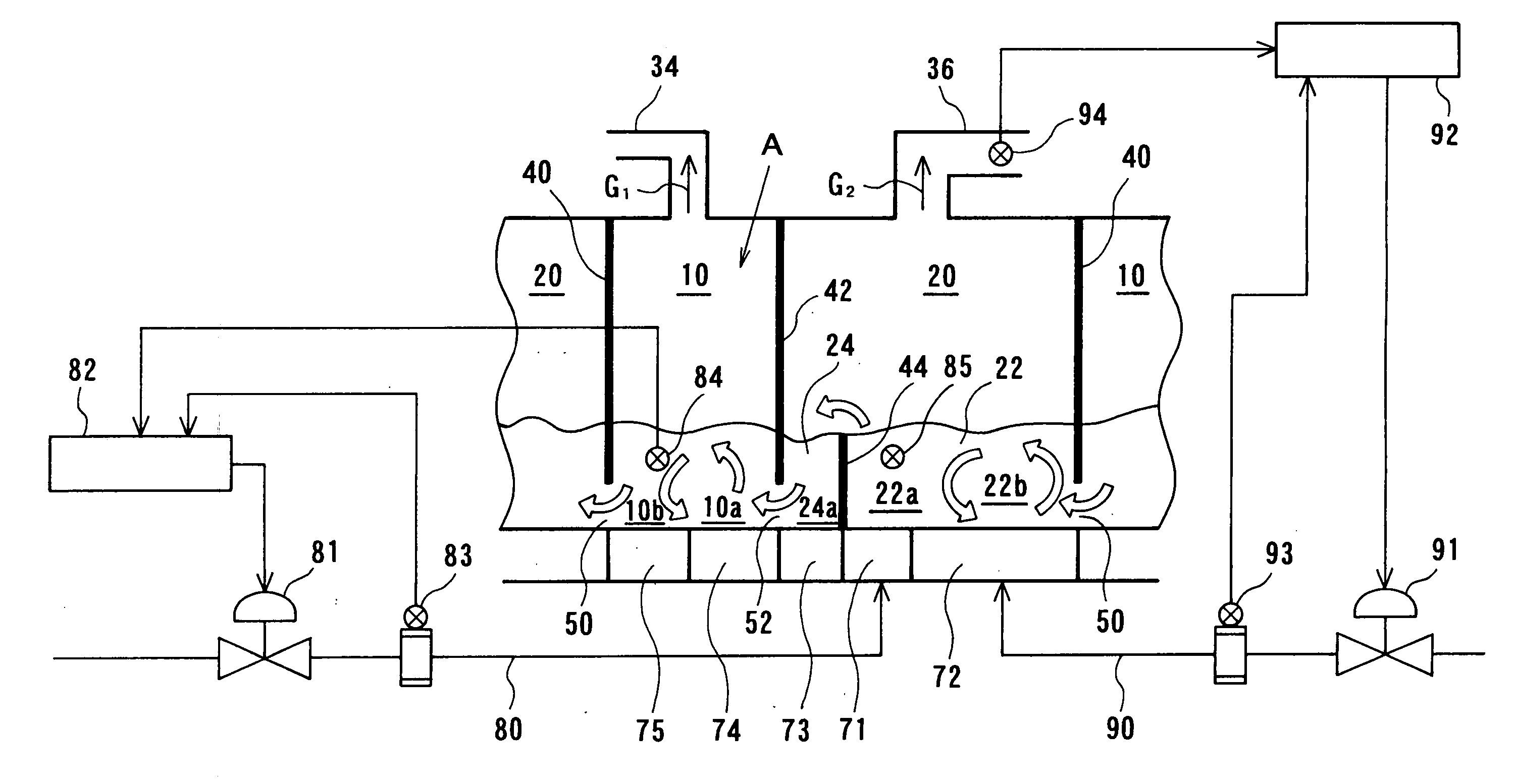
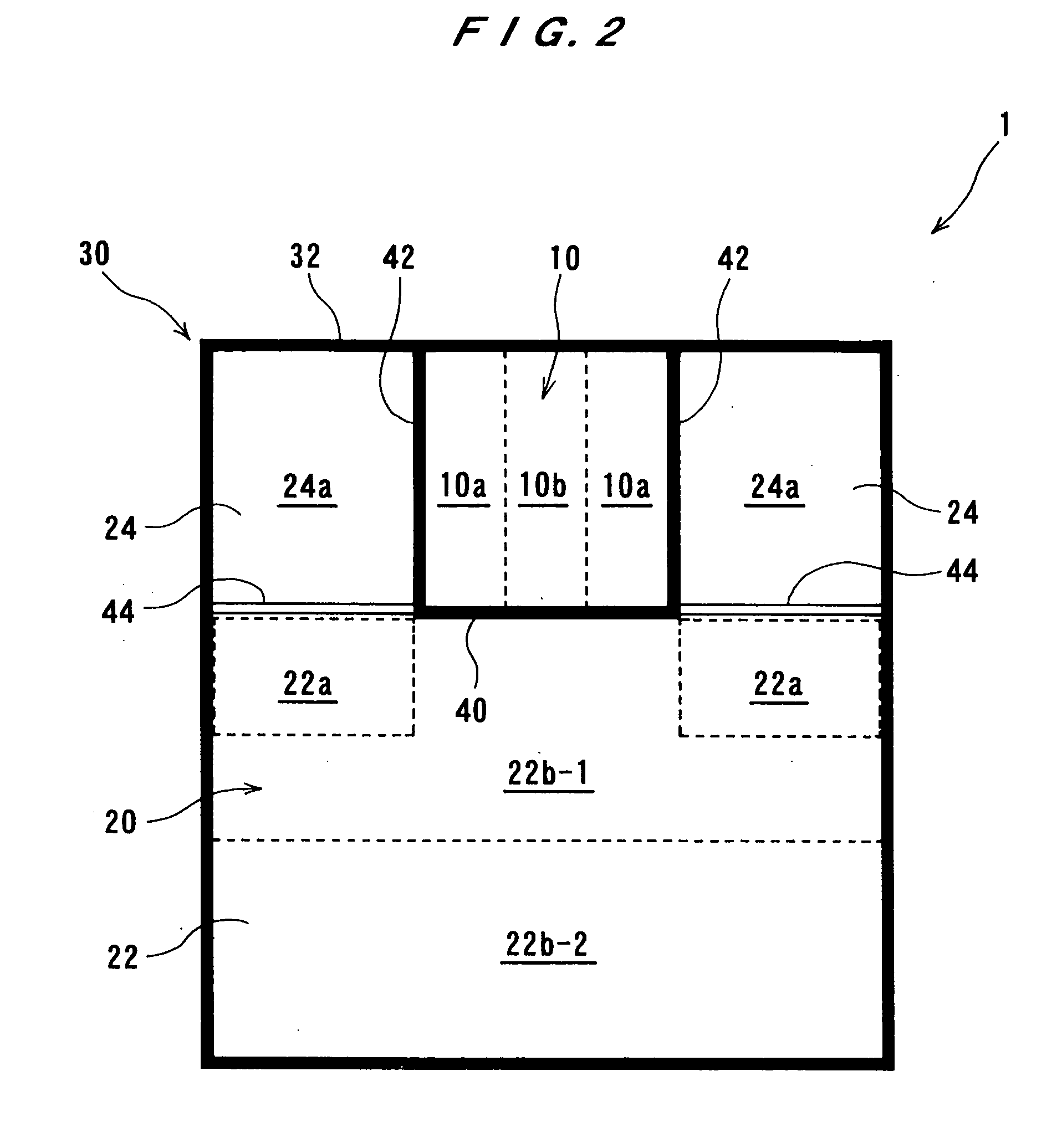
[0018] A fluidized-bed gasification furnace according to an embodiment of the present invention will be described below with reference to FIGS. 1, 2, and 3. Like or corresponding parts are denoted by like or corresponding reference numerals throughout drawings, and will not be described below repetitively.

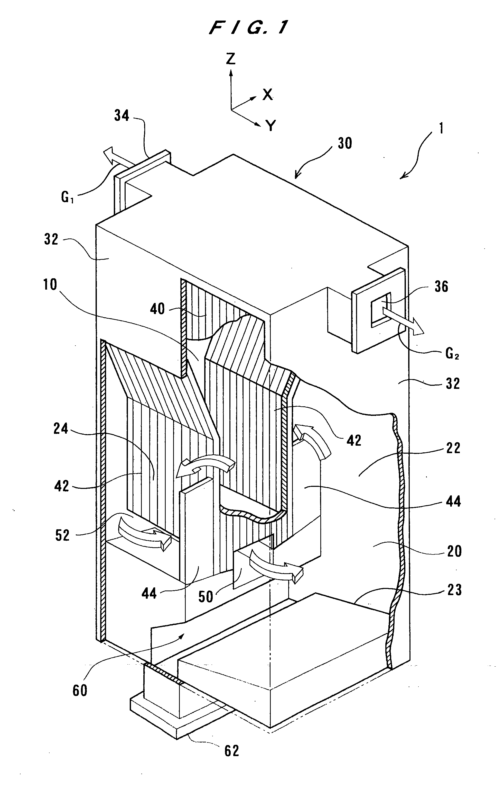
[0019]FIG. 1 is a perspective view showing a fluidized-bed gasification furnace 1 according to an embodiment of the present invention. In FIG. 1, the fluidized-bed gasification furnace 1 is illustrated as being partially cut away so as to show an internal structure of the fluidized-bed gasification furnace 1. In a rectangular coordinate system XYZ, a horizontal plane is represented by XY, and a vertical axis is represented by Z. An axis Y is directed to a front of the fluidized-bed gasification furnace 1. The fluidized-bed gasification furnace 1 is configured so as to be symmetrical with respect to the axis Y. As shown in FIG. 1, the fluidized-bed gasification furnace 1 is formed ...


PUM


Abstract

A fluidized-bed gasification furnace has a gasification chamber for fluidizing a fluidized medium therein and pyrolyzing a material in the fluidized medium to produce a pyrolysis gas and a pyrolysis residue. The fluidized-bed gasification furnace also has a combustion chamber having a combustion portion for fluidizing a fluidized medium therein and combusting the pyrolysis residue to heat the fluidized medium and a settling portion disposed adjacent to the combustion portion and the gasification chamber for settling the heated fluidized medium therein. The fluidized-bed gasification furnace includes a first passage for introducing the pyrolysis residue from the gasification chamber to the combustion chamber together with the fluidized medium, a second passage for introducing the heated fluidized medium in the combustion chamber from the settling portion of the combustion chamber to the gasification chamber, and a first diffusion device for supplying a fluidizing gas to a first region in the combustion portion adjacent to the settling portion of the combustion chamber to move the fluidized medium from the combustion portion to the settling portion. The fluidized-bed gasification furnace also includes a circulation controller operable to adjust a flow rate of the fluidizing gas supplied from the first diffusion device to control a circulation amount of the fluidized medium.

Description

CROSS-REFERENCE TO RELATED APPLICATIONS [0001] This application claims the benefit of priority of U.S. provisional application 60 / 698,930, filed Jul. 14, 2005.BACKGROUND OF THE INVENTION [0002] 1. Field of the Invention [0003] The present invention relates to a fluidized-bed gasification furnace, and more particularly to a fluidized-bed gasification furnace suitable for generating a gas from a material such as various wastes and solid fuel. Further, the present invention also relates to a method of pyrolyzing and gasifying a material with such a fluidized-bed gasification furnace. [0004] 2. Description of the Related Art [0005] There has heretofore been known a fluidized-bed gasification furnace for pyrolyzing various wastes or solid fuel such as coal to generate a product gas. In such a fluidized-bed gasification furnace, for example, the amount of oxygen or air to be supplied to the gasification furnace, which is one of various factors relating to reaction, is varied to change a t...

Claims


Application Information

Patent Timeline
IPC IPC(8): F27B15/00
CPCY02E50/30F27B14/10
Inventor HASHIMOTO, HIROSHITOYODA, YUKI
Owner EBARA CORP
Why Eureka
Try Eureka