Support structure for radiative heat transfer

a support structure and radiative heat transfer technology, applied in the direction of transportation and packaging, coatings, layered products, etc., can solve the problems of inability to achieve many applications successfully, additional correction cycles, affecting the cost and perhaps variability of friction performance of brakes, etc., to speed up chemical reactions, reduce the total number of cycles, and increase the effect of uniform weight pickup

Inactive Publication Date: 2007-01-18
HONEYWELL INT INC
View PDF10 Cites 25 Cited by
  • Summary
  • Abstract
  • Description
  • Claims
  • Application Information

AI Technical Summary

Benefits of technology

[0013] The present invention also provides a solution which ameliorates the necessity for multiple CVD cycles to meet minimum density requirements with large annular preforms. This solution involves positioning a structural member inside of the cylinder described by the inside diameters of the stacked preforms. This aspect of the present invention is illustrated in FIG. 1. The structural member that is positioned inside the stacked preforms in accordance with the present invention is selected to provide a “black body” or radiative substrate for absorption of heat. The passive heat distribution element is composed either of a thick graphite shaft or of a thick previously densified carbon-carbon shaft. This passive heat distribution element may be solid, or it may be a hollow cylinder, filled, for instance, with annular graphite rings or with previously densified C-C filler discs arranged with no spacers between them. The heat absorbed by this central structural member is in turn radiated to the preforms through their inside diameters. The transmission of heat from the central structural member speeds up chemical reactions occurring in the gases within the carbon-carbon composite preforms, thus making each CVD cycle more efficient, and reducing the total number of cycles necessary to raise the density of the preforms to a given target level. In accordance with the present invention, the central structural member may be made of graphite or of carbon-carbon composite material.
[0014] During the densification process, the passive heat distribution element absorbs a large portion of the heat in the furnace and radiatively and uniformly distributes the heat to the surrounding stack of preforms. The gaps between the walls of the apparatus and the preform discs are preferably kept small, so that the reactant gas flows uniformly around the preform discs being densified, and is forced through the preforms. This invention provides greater and more uniform weight pickup throughout the stacks. That is, in accordance with this invention, all of the preforms in a given densification batch are more uniform in density than are the preforms in a comparable batch made by a process that has no heat distribution element in the center of the furnace muffle. This uniformity results in a higher overall average density for the batch of preforms.

Problems solved by technology

CVI / CVD cycles are an important cost factor in the manufacture of carbon-carbon composite preforms.
This is not, however, successfully achieved in many applications.
This results in the center stacks not densifying to the same extent as do the stacks near the walls, which results in the need for additional correction cycles and / or in a potential for undesired microstuctures impacting cost and perhaps variability in friction performance of the brakes.

Method used


Image

  • Support structure for radiative heat transfer
  • Support structure for radiative heat transfer
  • Support structure for radiative heat transfer

Examples


Embodiment Construction

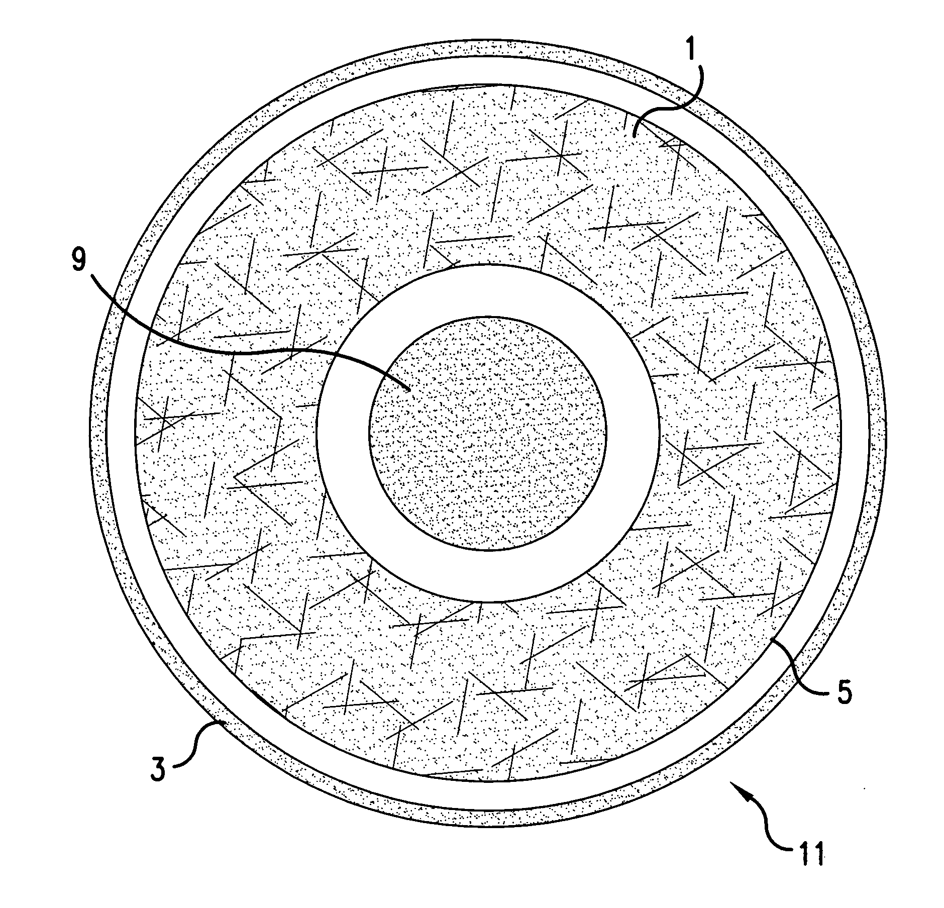
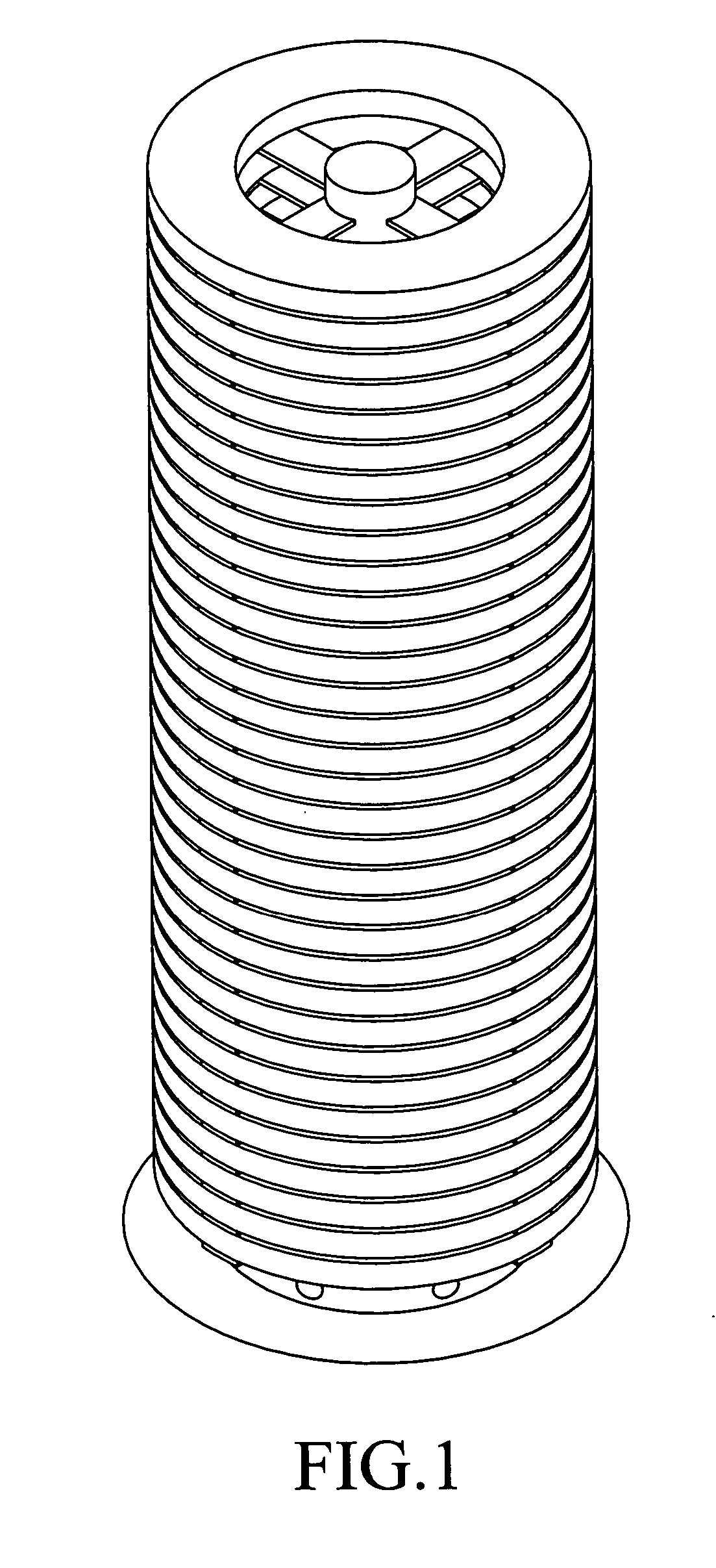
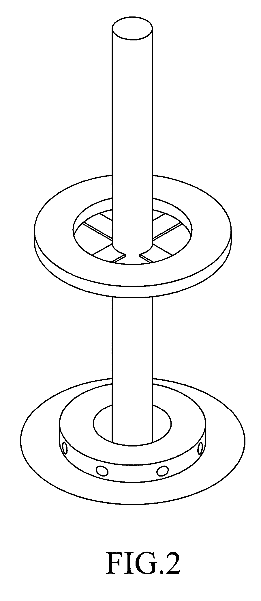
[0022] One embodiment of the present invention is a method for densifying a porous carbon preform. The method includes the steps of: providing an apparatus charged with at least one stack of annular porous carbon-carbon composite preforms, the preforms being separated from one another by spacers emanating from a passive heat distribution element centrally located within a cylindrical space formed by the stack of annular preforms; locating the charged apparatus in a furnace at a temperature in the range of 950-1100° C. and a pressure in the range of 5-40 torr; and circulating a carbon-containing gas reactant through the apparatus for from 150 to 900 hours. In accordance with the present invention, the preforms are densified with less than 1% total physical damage due to the weight of the preforms being treated than are a batch of preforms made by an otherwise identical process that does not separate preforms from the preforms immediately above and below them by spacer elements compri...


PUM

PropertyMeasurementUnit
pressureaaaaaaaaaa
temperatureaaaaaaaaaa
massaaaaaaaaaa

Abstract

Method for densifying porous carbon preforms. The method including: providing an apparatus charged with at least one stack of annular porous carbon-carbon composite preforms, the preforms being separated from one another by spacers emanating from a passive heat distribution element centrally located within a cylindrical space formed by the stack of annular preforms; locating the charged apparatus in a furnace at a temperature of 950-1100° C. and a pressure of 5-40 torr; and circulating a carbon-containing gas reactant through the apparatus for 150 to 900 hours. Also, an apparatus for practicing this method. The preforms are densified with less physical damage due to the weight of the preforms being treated than are preforms made by otherwise identical processes that do not separate preforms from the preforms immediately above and below them by spacer elements comprising tabs or shelves emanating from a central passive heat distribution structural member.

Description

[0001] This application claims the 35 U.S.C. §119(e) benefit of provisional application Ser. No. 60 / 698,924, filed Jul. 14, 2005. The entire disclosure of Ser. No. 60 / 698,924 is expressly incorporated by reference in the present application.FIELD OF THE INVENTION [0002] This invention concerns the manufacture of annular carbon-carbon composite preforms, and more specifically, chemical vapor infiltration and deposition (CVI / CVD) processes used in their manufacture. This invention provides an improved apparatus which can be used to carry out highly uniform CVI / CVD processes without occasioning damage such as warping or indentation in carbon-carbon composite preforms being densified by such processes. BACKGROUND OF THE INVENTION [0003] Carbon-carbon composite preforms are employed to produce, for instance, brake discs. Carbon-carbon composite preforms are made by densifying a fibrous substrate that has the approximate shape of the preform to be manufactured. This densification process ...

Claims


Application Information

Patent Timeline
Patent Type & Authority Applications(United States)
IPC IPC(8): B32B9/00
CPCC04B35/83C04B2235/614C23C16/045Y10T428/30C23C16/4583C23C16/46C23C16/26
Inventor ARICO, ALAN A.WAGHRAY, AKSHAYPARKER, DAVID E.
Owner HONEYWELL INT INC
Why Eureka
Try Eureka