Power-enabled connector assembly and method of manufacturing
- Summary
- Abstract
- Description
- Claims
- Application Information
AI Technical Summary
Benefits of technology
Problems solved by technology
Method used
Image
Examples
first embodiment
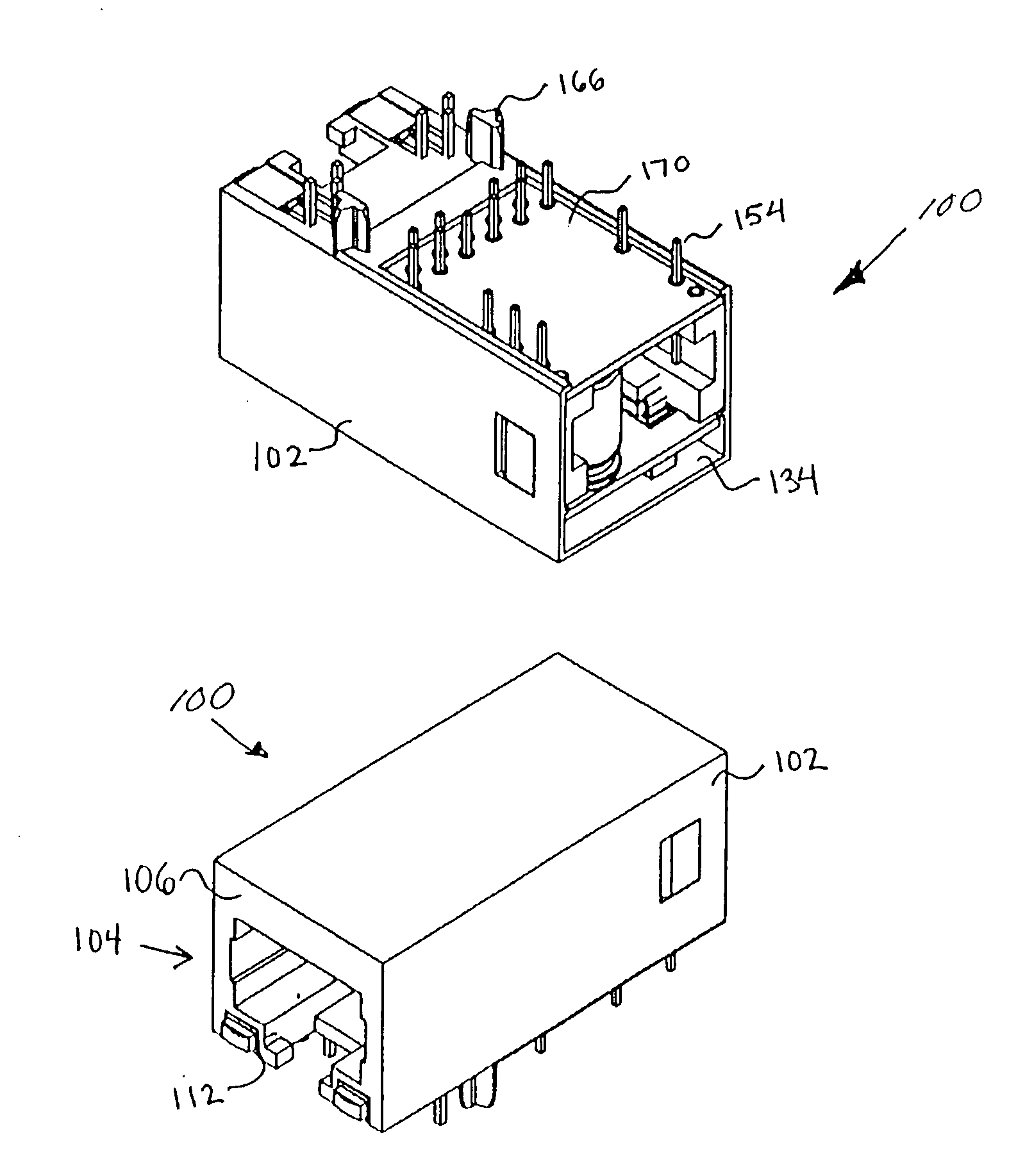
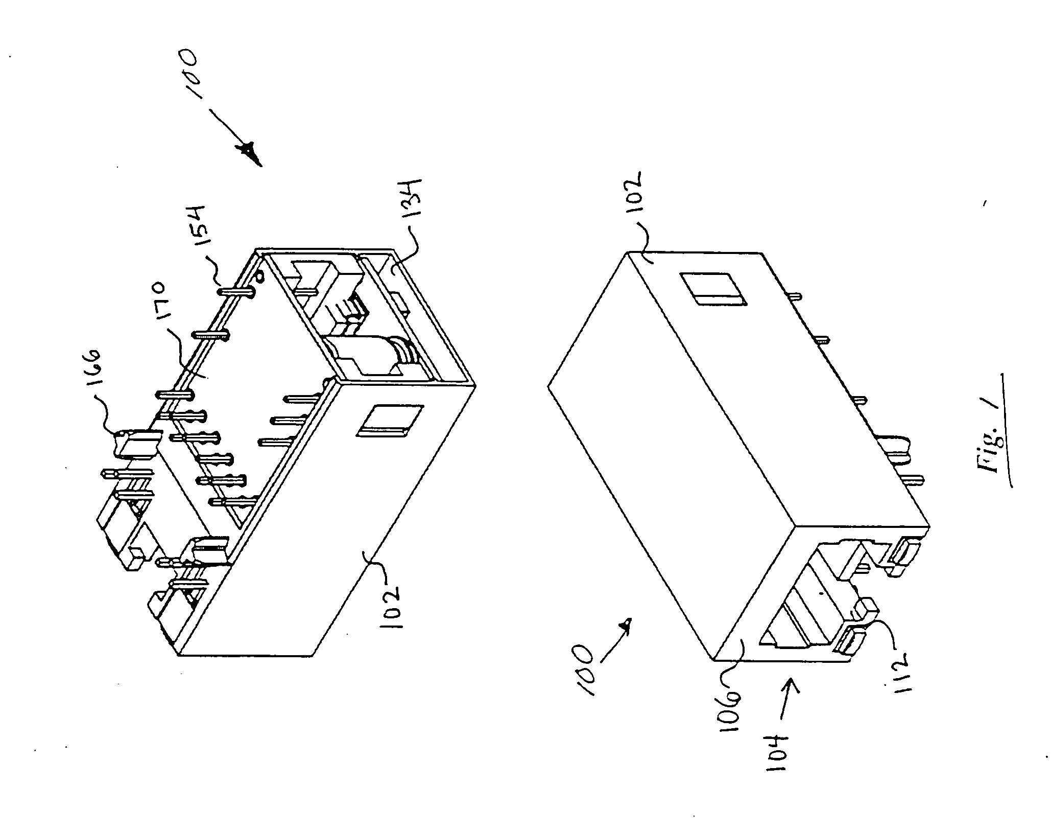
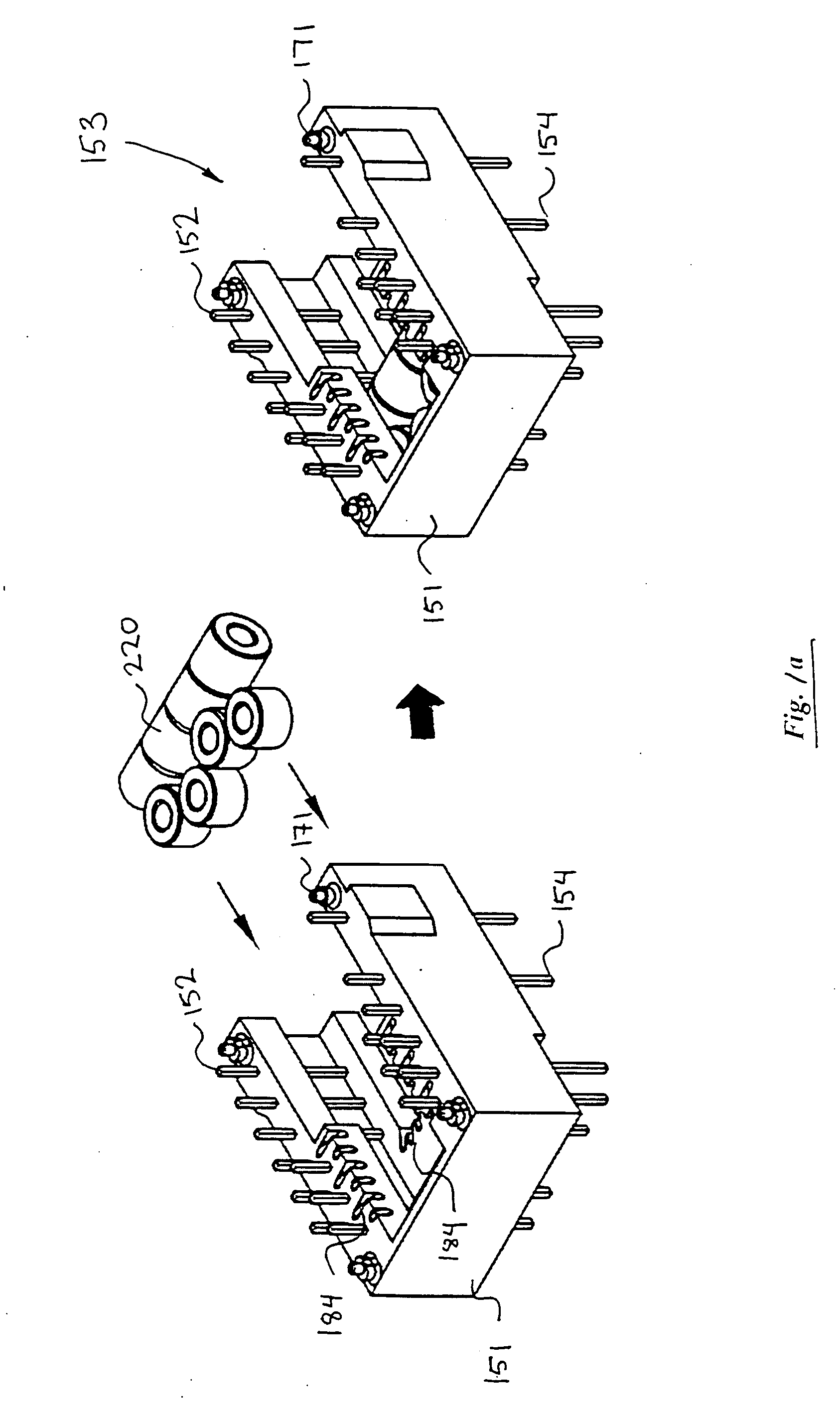
[0070] Single-Port Embodiment Referring now to FIGS. 1-1f, the connector assembly of the present invention is described. It will be appreciated that while described primarily in the context of an RJ-type modular jack (e.g., RJ-45 jack), the invention is in no way limited to such configurations, and may be more broadly applied to other types and form factors of connector.
[0071] As shown in FIG. 1, the exemplary assembly 100 generally comprises a connector housing element 102 having an individual connector 104 formed therein. The front wall 106 of the connector 104 is generally coplanar, such that a modular plug may be inserted into the plug recess 112 formed in the connector 104 without physical interference. Note also that as used herein, the term “front” is relative to the disposition of the connector. For example, in the context of a vertical mounted connector (not shown), the term front wall would more appropriately be described as a “top wall”.
[0072] The plug recess 112 is adap...
second embodiment
[0102] The connector assembly 100 with LEDs 190 may further be configured to include noise shielding for the individual LEDs if desired. In one embodiment, the LED shielding is accomplished by forming a thin metallic (e.g., copper, nickel, or copper-zinc alloy, etc.) layer on the interior walls of the LED recesses 194 (or even over the non-conductive portions of LED itself) prior to insertion of each LED. In a second embodiment, a discrete shield element (not shown) which is separable from the connector housing 102 can be used, each shield element being formed so as to accommodate its respective LED and also fit within its respective recess 194. In yet another embodiment, an external noise shield may be fabricated and deformed within the recesses 194 so as to accommodate the LEDs 190 on the outer surface of the shield, thereby providing noise separation between the LEDs and the individual connector conductors 120. A myriad of other approaches for shielding the connectors from the LE...
third embodiment
[0140]FIG. 2c illustrates the invention. In this embodiment, the power control circuitry utilizes two controllers 282, 283 (e.g., PoE integrated circuits, such as the Texas Instruments® TPS2375 devices) connected in parallel. One salient distinguishing feature for this configuration allows the apparatus utilizing this circuitry to handle a higher power output. In the illustrated embodiment, an output power of 30 Watts is achievable (with maximum current input of 350 mA continuous) as opposed to the approximately 15 Watts available under the embodiments shown in FIGS. 2a, 2b. A 4-wire choke 284 between the two bridge rectifier outputs and the controller circuit's inputs may also be utilized, which is especially desirable for EMI suppression. Also, in the exemplary embodiment shown in FIG. 2c, the “power good” outputs 287 are advantageously tied together so that if either output is not available, “power good” status is not asserted. It will be appreciated, however, that other logical ...
PUM
 Abstract
Description
Claims
Application Information
 - R&D
- Intellectual Property
- Life Sciences
- Materials
- Tech Scout
- Unparalleled Data Quality
- Higher Quality Content
- 60% Fewer Hallucinations
Browse by: Latest US Patents, China's latest patents, Technical Efficacy Thesaurus, Application Domain, Technology Topic, Popular Technical Reports.
© 2025 PatSnap. All rights reserved.Legal|Privacy policy|Modern Slavery Act Transparency Statement|Sitemap|About US| Contact US: help@patsnap.com


