Vacuum system with separable work piece support

US7025863B2Inactive Publication Date: 2006-04-11OERLIKON SURFACE SOLUTIONS AG PFAFFIKON

Image

  • Vacuum system with separable work piece support
  • Vacuum system with separable work piece support
  • Vacuum system with separable work piece support

Examples


Embodiment Construction

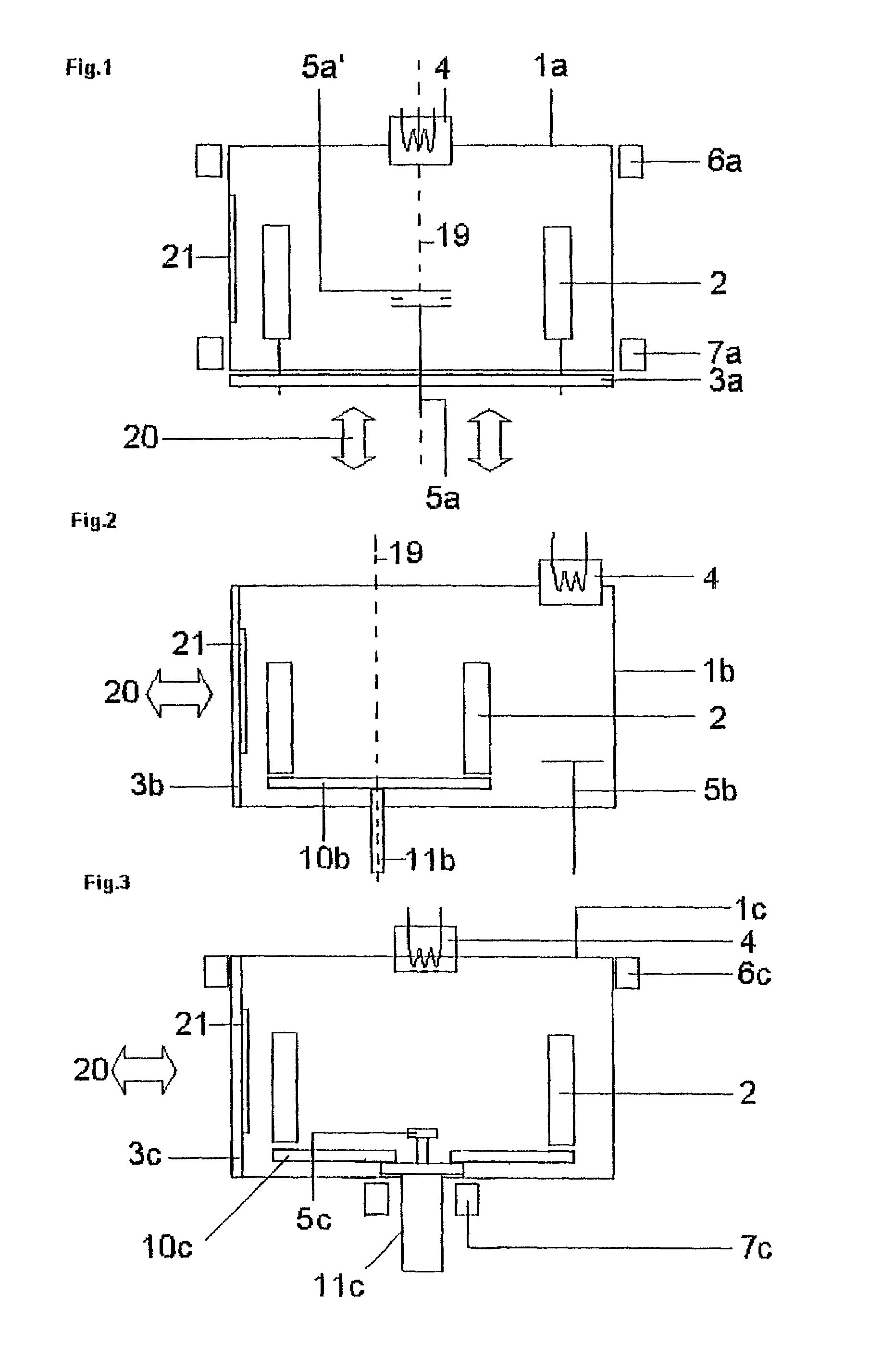
[0026]FIG. 1 shows a schematic representation of a vacuum coating device for large-scale industrial application according to the state of the art. Ionization chamber 4 and anode 5 are disposed along central axis 19 of treatment chamber 1a. The anode 5 can either be introduced from below through the system bottom as shown in 5a or from above as shown in 5a′. For stabilization of the low voltage arc, an upper coil 6a and a lower coil 7a are additionally attached to the system. The rotatably-supported work piece holders 2 are either fastened directly on the system bottom, constructed as a loading opening 3a, or on a work piece support (not shown) that is also rotatably-mounted on loading opening 3a. This makes it possible for the loading and unloading process (symbolically shown by the movement arrow 20) to be carried out merely by shifting the loading opening 3a downward. The resulting disadvantages are a high overall height of the device and a corresponding space requirement, as well...


PUM

PropertyMeasurementUnit
Pressureaaaaaaaaaa
Pressureaaaaaaaaaa
Bias potentialaaaaaaaaaa

Abstract

A vacuum system for the treatment of work pieces has an evacuatable treatment chamber having a centrally disposed low voltage arc discharge arrangement and laterally disposed loading opening. A coupling device between the work piece support and a receiving device on the system side allows simplified loading and removal of the work pieces to be treated along with the support by simply lifting onto or lowering from the receiving device.

Description

BACKGROUND OF THE INVENTION[0001]The present invention relates to a vacuum system for the treatment of work pieces having an evacuatable treatment chamber in whose central axis a low voltage arc discharge arrangement is disposed and at least one coating source attached to one lateral wall of the treatment chamber, as well as a work piece support on which work pieces can be mounted.[0002]It is known in the art of vacuum coating to perform cleaning and / or heating steps for various vacuum treatment processes before and / or after vacuum coating. Such steps are particularly necessary in order to give a deposited layer a good adhesive strength. This is especially important for applications where work pieces, particularly tools and parts subject to high mechanical stresses, are to be coated with a wear-resistant hard coating. Such coatings are often used in making tools, for example drills, milling cutters, and shaping tools, and in making parts such as toothed gears, needles for injection ...

Claims


Application Information

Patent Timeline
11 Apr 2006
Publication
US7025863B2
IPC
H01L21/00; C23C16/00; C23C14/24; C23C14/32; C23C14/34; C23C14/50; H01J37/32
CPC
C23C14/325; C23C14/3478; H01J37/32752; H01J37/32055; C23C14/505
Inventors
SEELI, ROGER; PEDRAZZINI, MAURO