

Polishing pad having edge surface treatment
- Summary
- Abstract
- Description
- Claims
- Application Information
AI Technical Summary
Benefits of technology
Problems solved by technology
Method used
Image

Examples
example 1
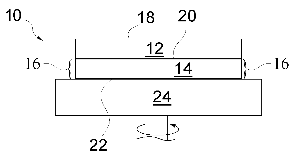
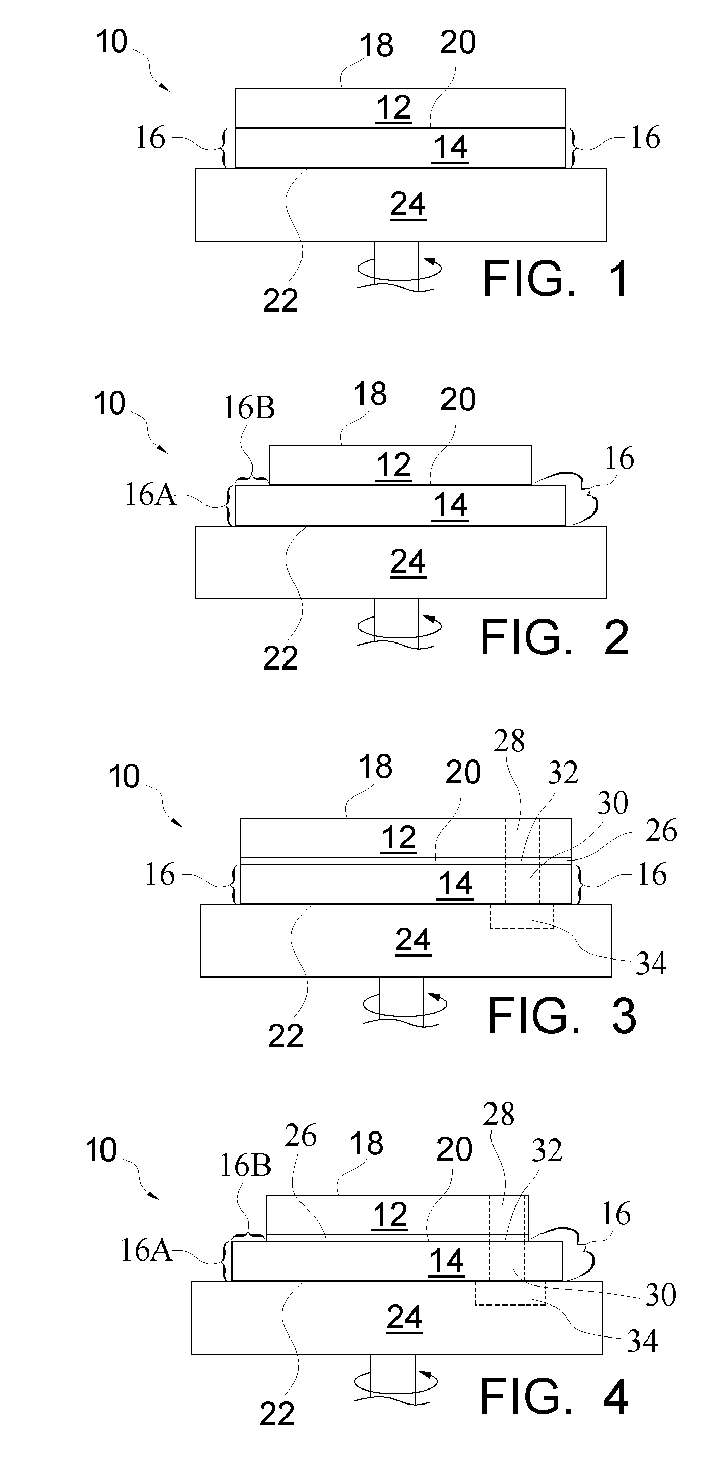
[0063] Using a small sponge, micronized polypropylene in powder form was wiped onto the sublayer 14 outer peripheral edge 16 of a stacked polishing pad 10 commercially obtained from Rodel, Inc., Newark, Del., under the trade name IC1400. The micronized polypropylene was commercially obtained from Lubrizol Corporation, Wickliffe, Ohio under the trade name Lanco PP1362D. Following application of the micronized polypropylene, the stacked pad 10 was immersed in slurry for one hour. The slurry was commercially obtained from Rodel, Inc., Newark, Del. under the trade name ILD 1300 Planarization Slurry. The pad 10 was removed from the slurry and the outer peripheral edge 16 was visually inspected. The outer peripheral edge 16 of the sublayer 14 appeared dry.
example 2
[0064] The process as described in Example 1 was carried out with the exception that the micronized polypropylene was replaced with hydrophobic fumed silica obtained from Degussa Corporation, Parsippany, N.J., under the trade name Aerosil R805. The outer peripheral edge 16 of the sublayer 14 appeared dry.
example 3
[0065] Hydrophobic fumed silica commercially obtained from Degussa Corporation, Parsippany, N.J., under the trade name Aerosil R202, was dispersed in acetone at a concentration of one (1) weight percent. Using a Texwipe clean room swab, No. TX761, commercially obtained from Fisher Scientific, Pittsburgh, Pa., the solution was applied to the sublayer 14 outer peripheral edge 16 of a 22.5-inch stacked polishing pad 10 commercially obtained from Thomas West, Incorporated, under the trade name WESTPADS, Model No. STT 711-C561-22.5. The sublayer 14 outer peripheral edge 16 was treated using 0.8 grams of the 1% solution. Following application of treatment solution, the pad 10 stack was held at ambient conditions for 2 hours then immersed in ILD 1300 slurry for one hour. The pad 10 was then removed from the slurry and the sublayer 14 outer peripheral edge 16 was visually inspected. The outer peripheral edge 16 of the sublayer 14 appeared dry.
PUM
 Abstract
Description
Claims
Application Information