

Ultrasonic surgical apparatus and method of driving ultrasonic treatment device
a treatment device and ultrasonic technology, applied in the field of ultrasonic surgical equipment and a driving method of ultrasonic treatment device, can solve the problems of often exceeding the desired value of the treatment device temperature, and achieve the effect of improving performan
- Summary
- Abstract
- Description
- Claims
- Application Information
AI Technical Summary
Benefits of technology
Problems solved by technology
Method used
Image

Examples
first embodiment
[0074] With reference to FIG. 1-25 and 57, a first embodiment of the ultrasonic surgical apparatus according to the present invention is described.
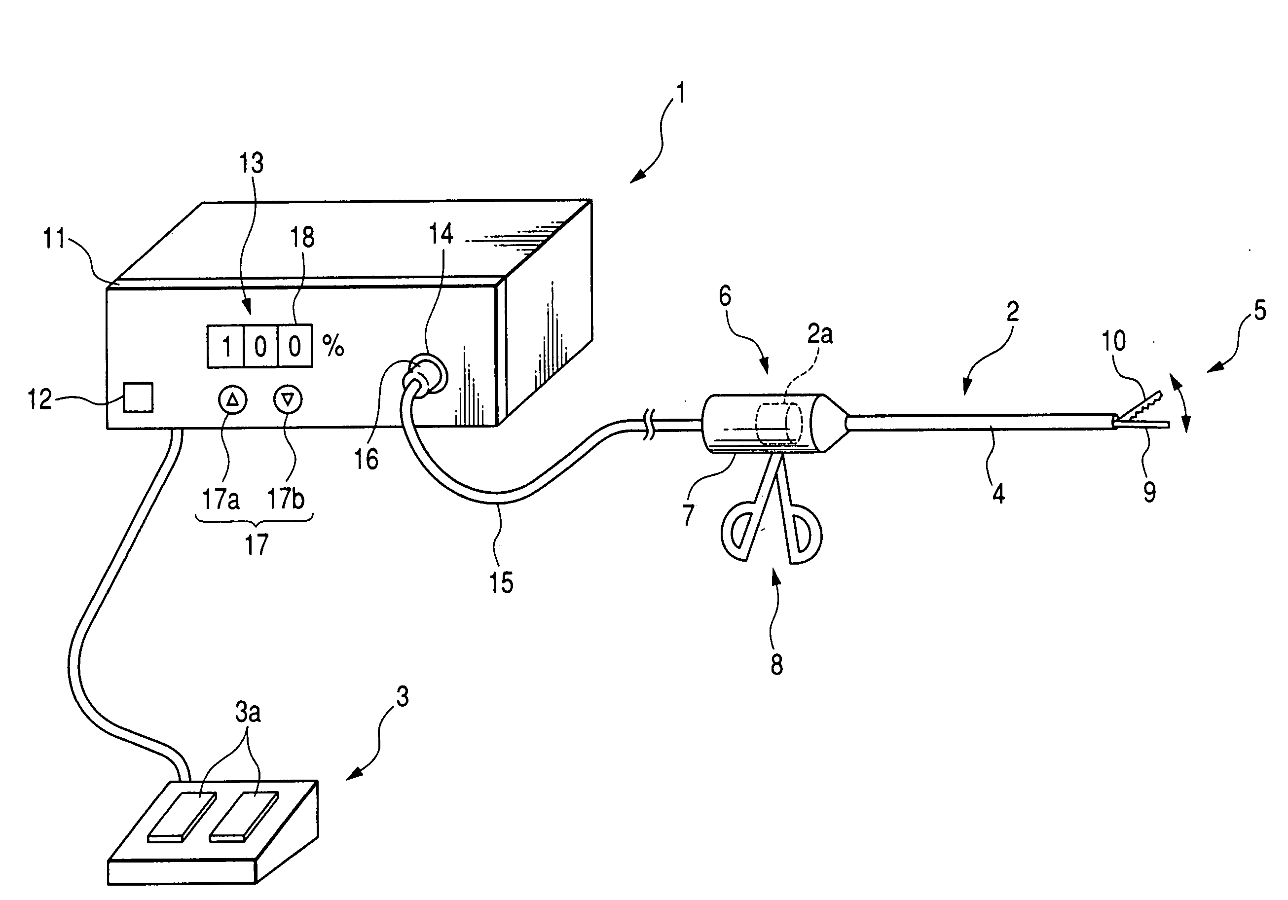
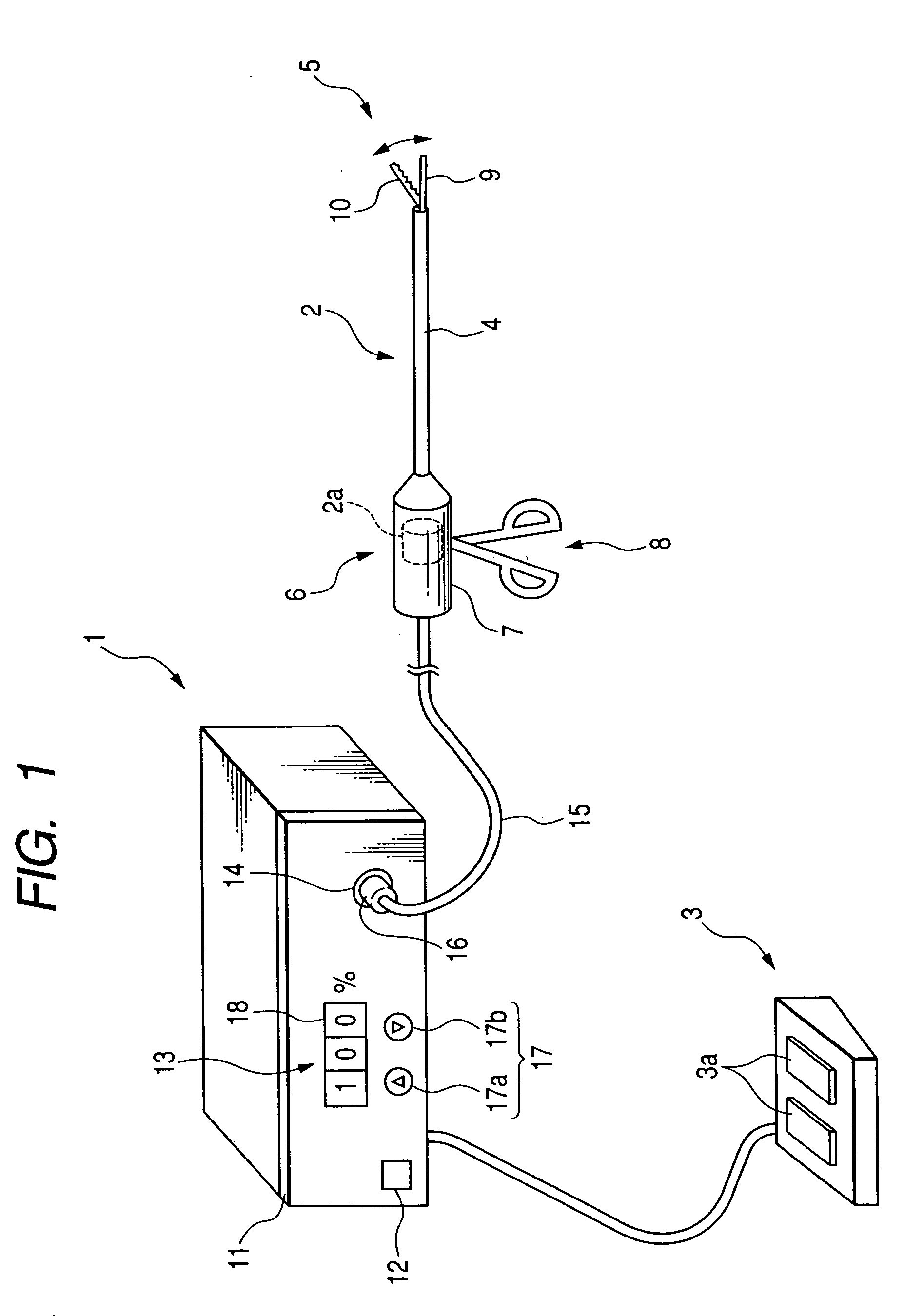
[0075]FIG. 1 shows an appearance of an entire arrangement of the ultrasonic surgical apparatus of a first embodiment. This ultrasonic surgical apparatus comprises a main unit 1, an ultrasonic treatment device (hereinafter referred to a handpiece) 2, and a foot switch 3. The handpiece 2 and the foot switch 3 are physically and electrically connected to the main unit 1.
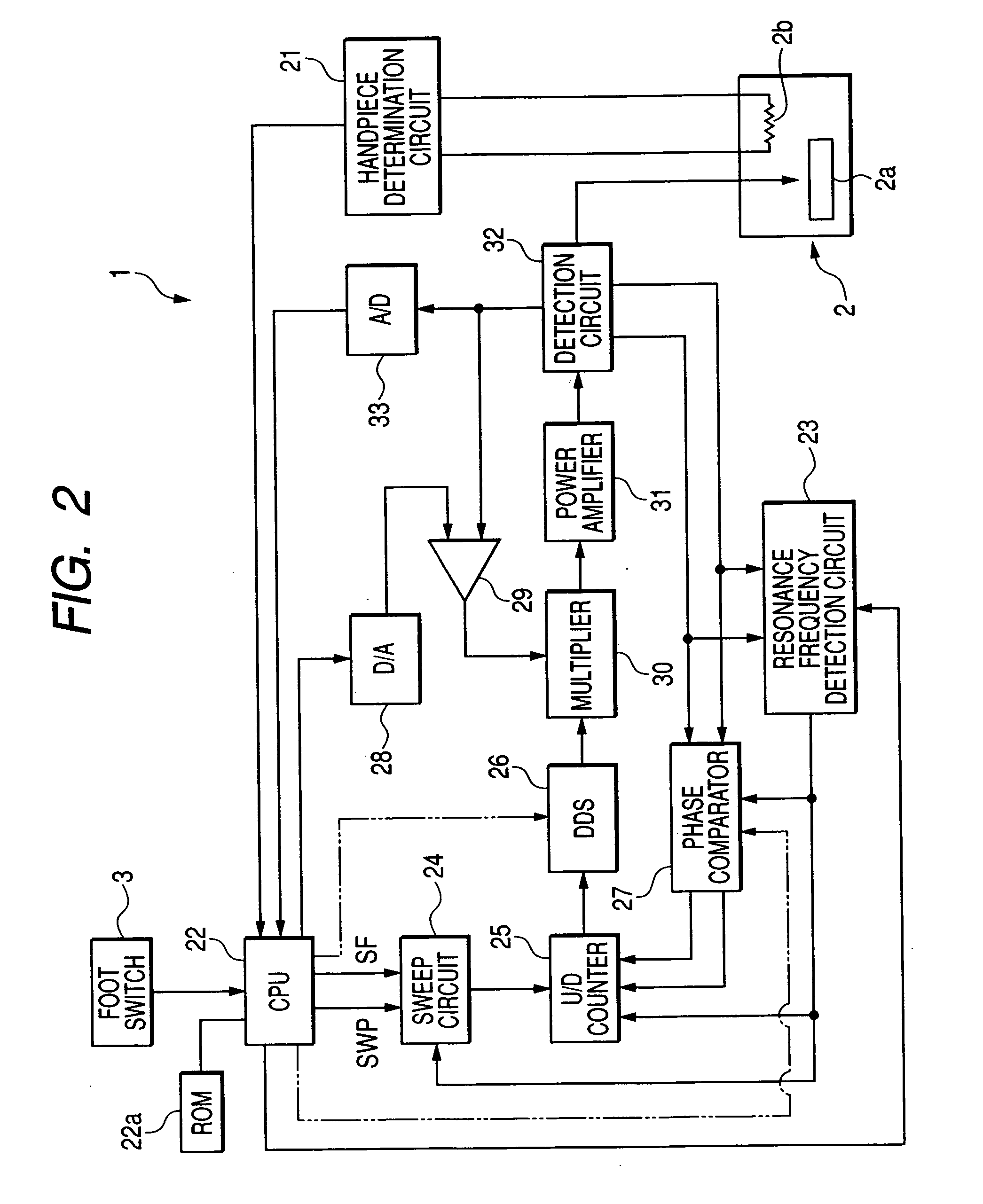
[0076] The main unit 1 drives the handpiece 2. The handpiece 2 is provided with an elongated sheath 4, with a treatment device 5 being provided at a tip thereof and an operating portion 6 being provided at a base (portion placed in an operator's hand) thereof. A case 7 for accommodating an ultrasonic transducer 2a (see FIG. 2), and an operation handle 8 are provided at the operating portion 6. The ultrasonic transducer 2a is adapted to generate mechanical vibration (longitu...
second embodiment
[0142] With reference to FIG. 26, a second embodiment of the ultrasonic surgical apparatus according to the present invention is described.
[0143]FIG. 26 is a block diagram illustrating an electric circuit configuration of an ultrasonic surgical apparatus, which is a modification of the configuration shown in FIG. 2. In this circuit configuration a ROM recorded with waveform pattern data is incorporated into a handpiece 2. The same components as in FIG. 2 are referred to by the same reference numerals, and description therefor is omitted.
[0144] In the circuit configuration shown in FIG. 26, a detection circuit 32a detects a current signal and a voltage signal, and supplies the current signal to an absolute value processing circuit 32b. The absolute value processing circuit 32b supplies an absolute value signal of the current signal to the comparator 29. Also, the detection circuit 32a supplies the current signal and the voltage signal to a rectangular waveform processing circuit 32...
third embodiment
[0151] With reference to FIG. 27, a third embodiment of the ultrasonic surgical apparatus according to the present invention is described.
[0152]FIG. 27 shows another example of a front panel for an operator to set a waveform pattern data PD.
[0153] A front panel 11A shown in FIG. 27 is provided with a pair of digital displays 18A, 18B, and a pair of switches 17A, 17B for increasing and decreasing output, which correspond to the respective digital displays. The switches 17A, 17B, respectively, comprise switches 17Aa, 17Ab and switches 17Ba, 17Bb for increasing and decreasing output. The display 18A is a display for indicating and setting a minimum output value, i.e. a ratio (%) of the minimum output value to a 100% maximum output value. An operator can set a desired minimum value by depressing the switches 17Aa, 17Ab observing a value indicated on the display 18A. In a similar fashion, the display 18B is a display for an operator to set a one-cycle duty ratio. An operator can set a ...
PUM
 Abstract
Description
Claims
Application Information