
Power supply controller

a power supply controller and power supply technology, applied in the direction of electric controllers, automatic control, instruments, etc., can solve the problems of sending errors and not only the failure of transmit/receive contact signals, and the failure of transmitting/receiving contact signals

Inactive Publication Date: 2007-01-18
HITACHI COMPUTER PERIPHERALS CO LTD
View PDF4 Cites 5 Cited by
  • Summary
  • Abstract
  • Description
  • Claims
  • Application Information

AI Technical Summary

Benefits of technology

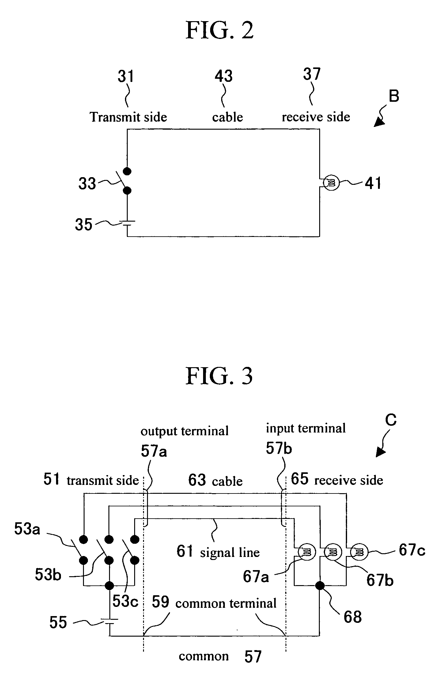
[0008] However, when communicating with contact signals between two devices; consisting of a device A and a device B, signals are seldom sent just from the device A to the device B, or just from the device B to the device A. Usually signals are also sent from the device B to the device A, and from the device A to the device B. In this case, the device A and the device B both function as the transmit side and as the receive side, and both possess a number of input terminals and output terminals. The transmit / receive method from the device A to the device B, and the transmit / receive method from the device B to the device A are not always the same at this time. For example, if utilizing the No. 1 transmit / receive method of FIG. 4 from the device A to the device B, and utilizing the No. 3 transmit / receive method from the device B to the device A, then only the device B possesses a power supply and yields the benefit that the size can be reduced since the device A does not include a power supply.
[0016] When a correct output cannot promptly be obtained in this way, error correction is performed and recovery is then attempted by retries, reconfiguration, and recovery processing according to the recovery flow in section 4.2 of “Introduction to High Reliability Technology for Computer Systems”. However, the correct outputs cannot be obtained from the system until recovery is complete. Methods where correct outputs cannot be obtained until recovery is complete are generally called active redundancy. Methods utilizing different types of redundancy belonging to this active redundancy are described in section 4.1.3 of “Introduction to High Reliability Technology for Computer Systems”. Methods classified as active redundancy generally possess the advantage of a low cost. However these methods also possess the great disadvantage that the system must be stopped during the period that correct outputs cannot be obtained. Though dependent on the type of communication method, the communication might be either interrupted or information containing errors might be communicated.
[0028] This invention makes the input side (receiving side) is capable of detecting when reliable signals cannot be generated due to an error occurring in the processing system for generating signals to be sent from the output (transmit) side. This invention therefore possesses the advantage that there is no need to stop the system even in a period where the control signals are unreliable and cannot be output correctly.

Problems solved by technology

In cases where the signal line is disconnected due for example to the cable connector coming loose, or cases where an error has occurred in the processor (processing system) that interprets the open / close of the contact signal according to the protocol and generates the signal to be sent and a reliable signal cannot be generated, then not only is transmit / receive of the contact signal disabled but a signal with errors is sent.

Method used


Image

  • Power supply controller
  • Power supply controller
  • Power supply controller

Examples


Embodiment Construction

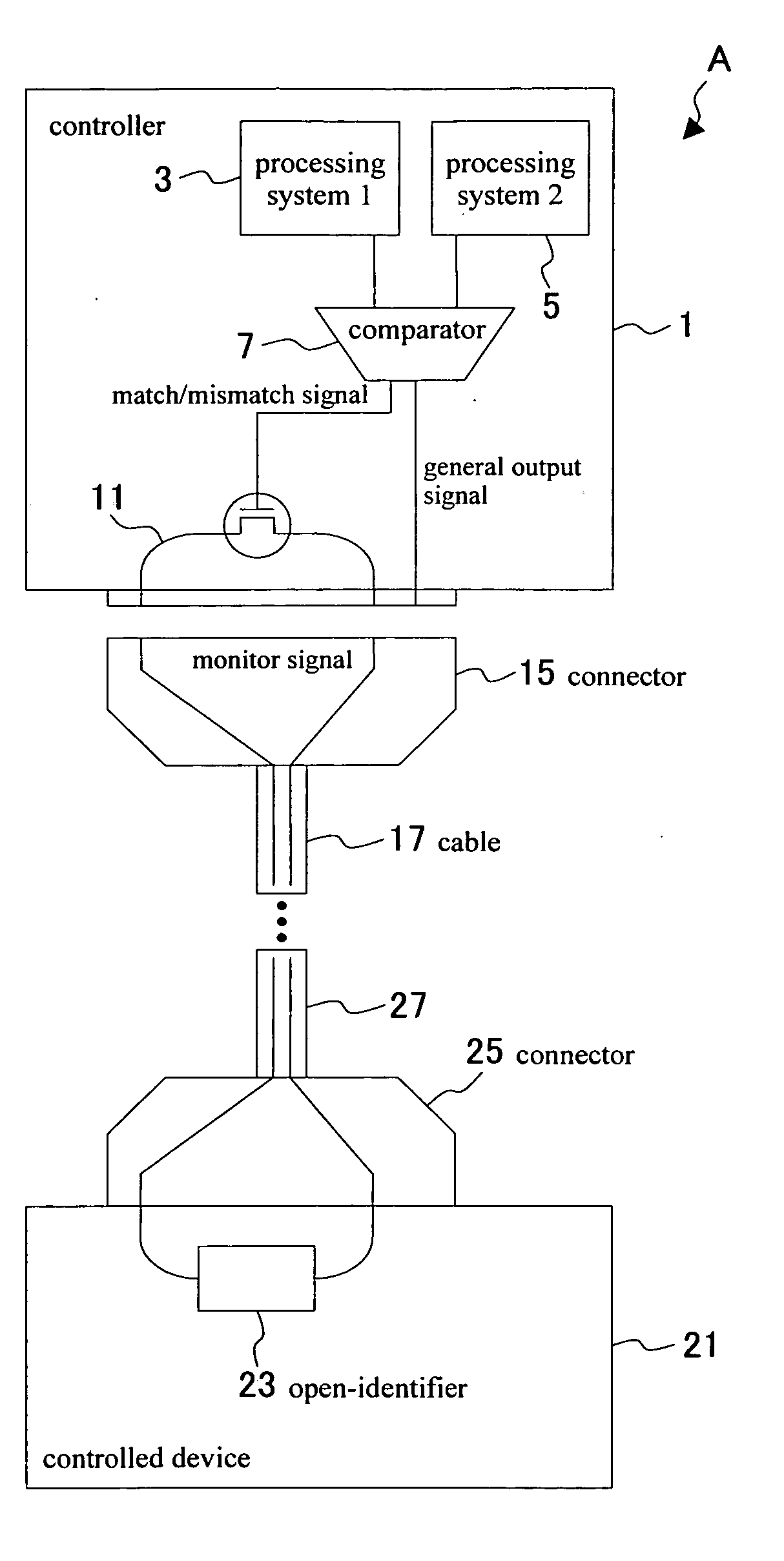
[0049] The embodiments of the controller of this invention are described next while referring to the accompanying drawings. The controller for example is a control device for a disk array. FIG. 7 is a function block diagram showing the functions of the control device of the embodiment of this invention. The controller 215 for the system E shown in FIG. 7 can communicate with the control terminal 201 via the serial (RS-232C) port 212 and the LAN 211. The controller 215 receives instructions from the control terminal 201 and controls the power supply from the four devices 217a to 217d by means of the contact signals. The controller 215 of this embodiment includes an HTTP server (web server) function, and is capable of communicating with the control terminal 201 possessing an HTTP client (for example, web browser) function.

[0050] The controller 215 of the embodiment of this invention includes the functions of an SNMP agent and can communicate with the control terminal 201 as the NMS (...


PUM


Abstract

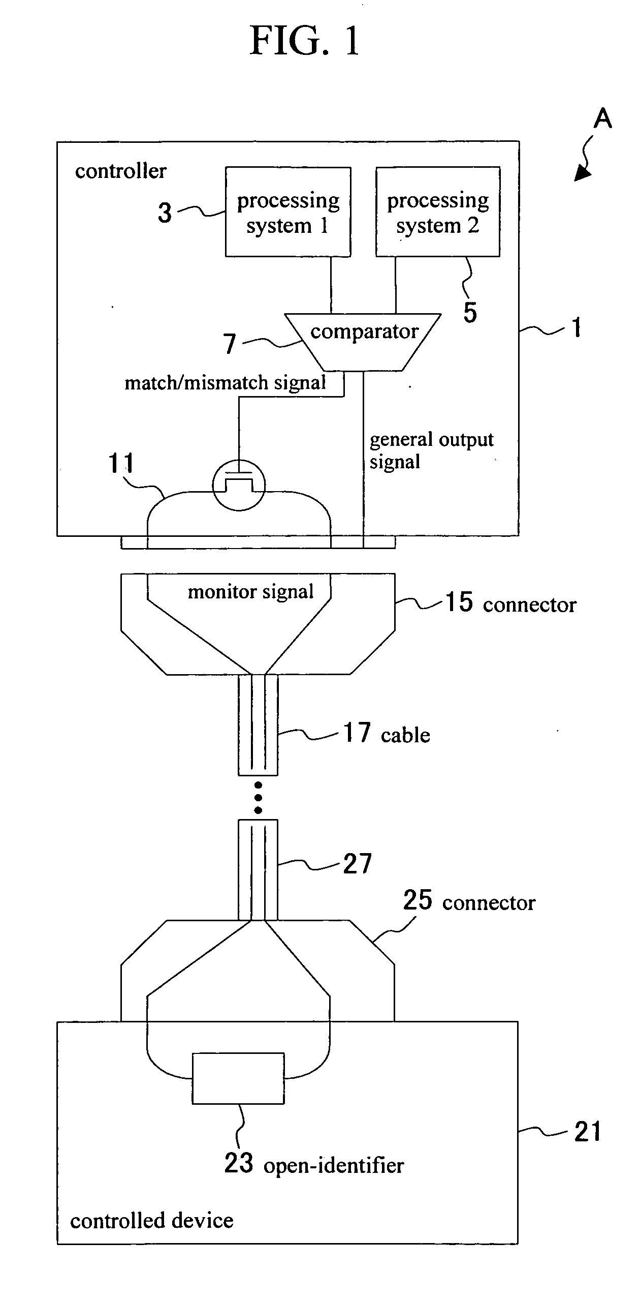
A power supply controller with a function to identify whether or not a signal that was output is reliable and to perform the necessary processing on the input side when an unreliable signal was sent that might adversely affect the input side in communication systems. A controller 1 and a controlled device 21 are connected at both ends of a cable 17 (27) with connectors. The controller contains a first processing system 1, a second processing system 2, and a comparator 7. The first processing system and the second processing system 2 are for example equivalent to microcomputers, etc. The comparator 7 compares the outputs of these two processors and generates a match / mismatch signal according to whether the outputs are a match or not. When the two outputs are a match then the outputs of these processors are reliable. However if the outputs are a mismatch then it signifies there is an error in one of these processing systems. Either of these processors outputs a general output signal separate from the match / mismatch signal. The general output signal may be output from either the first processing system or the second processing system without passing through the comparator. The general output signal is converted to a contact signal. The match / mismatch signal functions to turn the monitor signal on the monitor signal line on and off. The actual connection for this (output signal line) is shown in the drawings. The monitor signal line forms a loop on the monitor signal line for the signal to move back and forth between the controller and the controlled device. The controlled device contains an internal open-identifier for sensing whether the control signal line is open or closed.

Description

FIELD OF THE INVENTION [0001] The present invention relates to power supply control technology for power supplies such as for power supply control of disk arrays and relates in particular to a power supply controller for sending and receiving contact signals as unreliable output signals that might adversely affect the input side in communication systems. BACKGROUND OF THE INVENTION [0002] In power supply control technology such as for disk arrays, whether or not the contact signal being sent and received is reliable has traditionally been an extremely critical problem. FIG. 2 is a drawing showing the concept of contact signal. In FIG. 2, the transmit side 31 includes a power supply 35 and a switch 33, and the receive side 37 contains a light bulb 41. These components are connected together forming an electrical circuit and can transmit signals by utilizing the opening and closing a switch on the transmit side according to the information to be sent, and the light bulb on the receive...

Claims


Application Information

Patent Timeline
IPC IPC(8): G05B11/01
CPCG05B23/0237
Inventor ABE, YUUICHITANIGUCHI, KIMIAKI
Owner HITACHI COMPUTER PERIPHERALS CO LTD
Learn More