
Self-regulating temperature control system

a temperature control system and self-regulating technology, applied in the direction of fluid circulation arrangement, refrigeration machines, lighting and heating apparatus, etc., can solve the problems of simply non-competitive cost parameters in the modern marketplace, and not efficient to cool the whole radar array associated, so as to achieve the desired level of operating efficiency and minimize the cost level

Inactive Publication Date: 2007-01-25
LOCKHEED MARTIN CORP
View PDF11 Cites 6 Cited by
  • Summary
  • Abstract
  • Description
  • Claims
  • Application Information

AI Technical Summary

Benefits of technology

[0010] The present invention is directed to a passive or active, self-regulating cooling and / or heating system and method for providing a desired level of operating efficiency at a minimized cost level when compared with known cooling / heating systems and methods. The self-regulating cooling / heating system and method can direct a cooling / heating medium, e.g. liquid, gas, medium that changes state or undergoes a phase transition, through only those portions of a system or device that are operationally hot or cold, while substantially ignoring those portions of the system or device that are not operationally hot or cold or are otherwise operationally cool or hot.
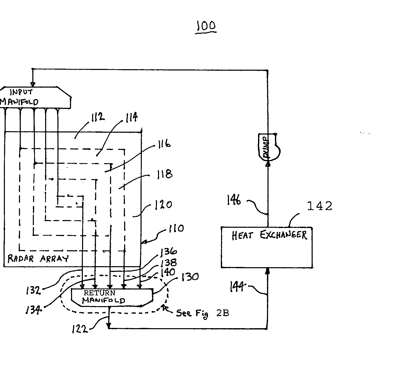
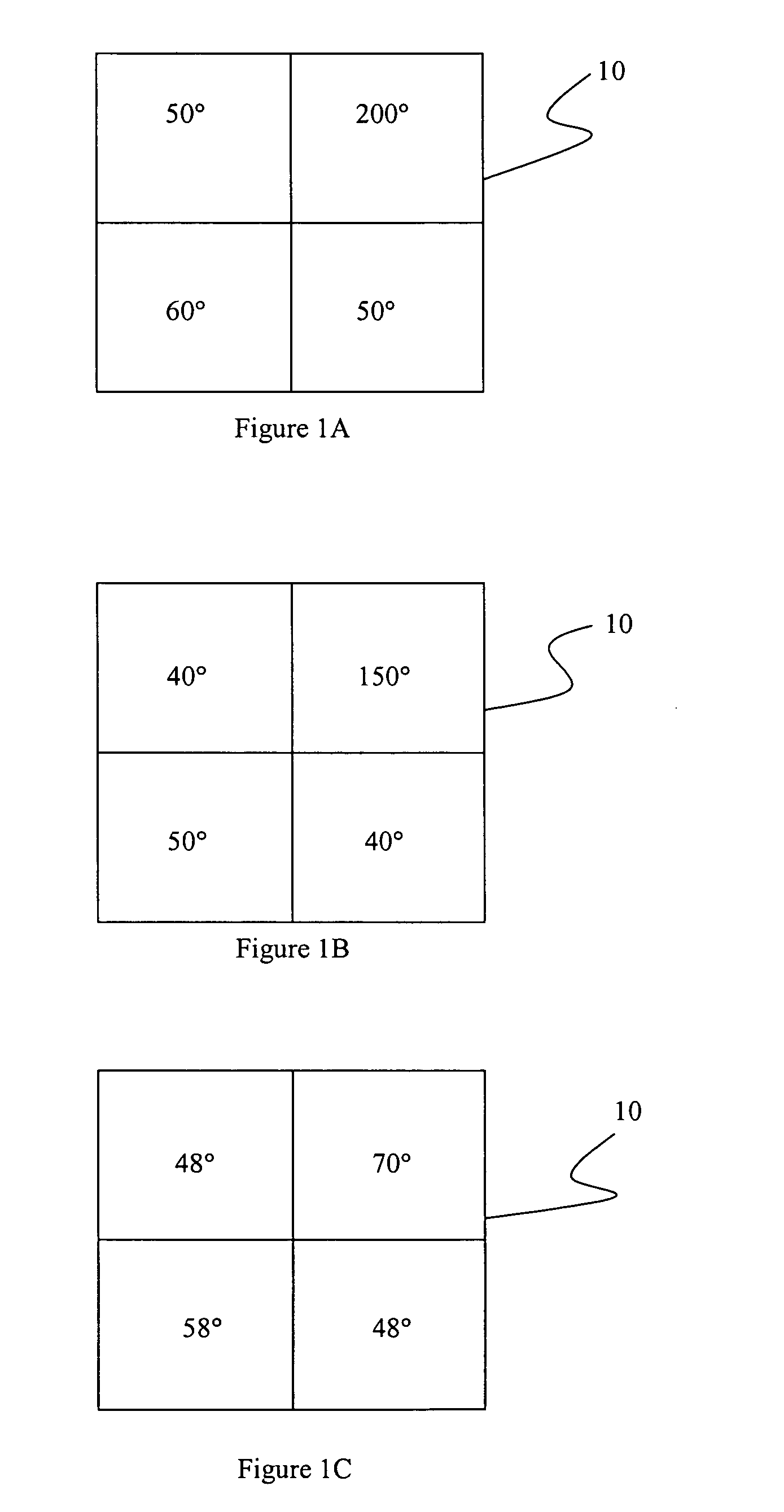
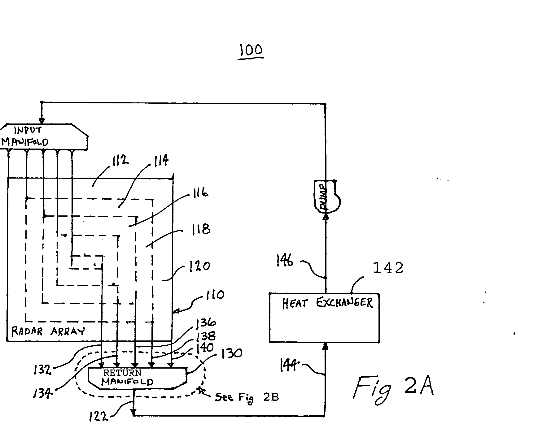
[0011] More specifically, one embodiment of the system or device is cooled in sections or portions that are independent from one another such that it is possible to selectively cool any one or more sections or portions, such as described herein before with reference to FIGS. 1A-1C. In one embodiment, the coolant or cooling medium is exhausted from each section of the system or device into a manifold having a plurality of input ports. Each input port receives the coolant or cooling medium solely from a predetermined single section. The manifold has a single output port that transfers the cooling medium into a heat exchanger wherein the cooling medium is cooled. Such heat exchangers are well known in the art, and so will not be discussed in further detail herein to preserve brevity and enhance clarity. The cooled medium is then pumped back into the system or device. Each manifold input can contain a distinct passive or active temperature controlled flow control device that reacts only to the temperature of the cooling medium passing through the passive or active flow control device. Each flow control device could just as easily be positioned at each input port or output port associated with the system or device to be cooled. In this manner, each section or portion of the device or system to be cooled will receive only that amount of cooling medium or coolant necessary to efficiently cool the respective section or portion that needs to be cooled. This process then can be seen to be self-regulating since each passive or active flow control device reacts to pass or restrict the amount of coolant passing through its respective section or portion of the system or device. The operating efficiency is thus improved since the maximum quantity of return coolant need not necessarily pass through each portion of the device or system to be cooled. Only those sections or portions requiring enhanced cooling will see enhanced coolant flow there through.

Problems solved by technology

Known cooling techniques can provide the desired efficiencies, but at cost parameters that are simply non-competitive in the modern marketplace.
Since these arrays are so very large, only certain portions of such displays are used at any given moment in time.
It is therefore not efficient to cool the whole radar array associated with the radar display unit, when instead, it is only necessary to cool that portion of the array that is being utilized, and thus is operating at an elevated temperature.

Method used


Image

  • Self-regulating temperature control system
  • Self-regulating temperature control system
  • Self-regulating temperature control system

Examples


Embodiment Construction

[0027] The embodiments described in detail herein below are directed to a self-regulating cooling (or heating) system and method for passively or actively providing a desired level of operating efficiency at a minimized cost level when compared with known cooling and heating systems and methods that employ active control techniques. The self-regulating cooling / heating system and method, as stated herein before, can direct a cooling or heating (fluidic) medium, e.g. liquid, gas, medium that changes state or undergoes a phase transition, through only those portions of a system or device that are operationally hot or cold, while substantially ignoring those portions of the system or device that are not operationally hot or cold or are otherwise operationally cool or hot.

[0028] Before moving to the Figures, it is important to note that the system or device to be cooled or heated is cooled or heated in sections or portions that are independent from one another such that it is possible t...


PUM


Abstract

A self-regulating cooling / heating system employs a variable flow manifold that allows the automatic re-direction of cooling / heating fluid (air, water, phase transition medium) to the areas of the cabinet or enclosure that requires the most cooling / heating. This enables a more efficient use of cooling / heating capability, sending the cooled / heated fluid to areas of greatest temperature differential, which will result in a greater amount of thermal energy being transferred to the cooling / heating medium. This technique yields more efficient electronics and systems.

Description

BACKGROUND OF THE INVENTION [0001] 1. Field of the Invention [0002] This invention relates generally to cooling and heating systems, and more particularly to a passively or actively temperature controlled, self-regulating method and system for cooling a liquid, gas, or phase transition medium to implement selective cooling of an operationally hot system or device, or heating of an operationally cold system or device in the same manner, to increase the system or device operating efficiency. [0003] 2. Description of the Prior Art [0004] The cooling of fluids is desirable in many applications. Internal combustion engines, for example, run more efficiently if relatively high temperature fuel is cooled before being introduced into the combustion chamber. [0005] Hydraulic systems function better with cooler hydraulic fluid. Oil lubrication systems are more effective when the oil is cooled. This is true in transmissions and other parts of a power train as well as for the internal lubricati...

Claims


Application Information

Patent Timeline
IPC IPC(8): F25B41/04
CPCF28D2021/0029F28F27/02F28F9/02F28F3/12
Inventor MONSON, ROBERT J.ABRAHAM, JOHN P.
Owner LOCKHEED MARTIN CORP
Learn More