Piezoelectric vibration gyro sensor and electronic device equipped with the same

a gyro sensor and gyro sensor technology, applied in the direction of turning-sensitive devices, acceleration measurement using interia forces, instruments, etc., can solve the problems of gyro vibration pieces being tilted in that direction, variations and changes in detection sensitivity of gyro sensors, etc., to achieve stable angularity, stable vibration characteristic of gyro vibration pieces, and well-balanced manner

Inactive Publication Date: 2007-01-25
SEIKO EPSON CORP
View PDF3 Cites 16 Cited by
  • Summary
  • Abstract
  • Description
  • Claims
  • Application Information

AI Technical Summary

Benefits of technology

[0008] An advantage of the present invention is to provide a supporting structure of a piezoelectric vibration gyro element, a gyro sensor, and an electronic device equipped with the same, which achieve a flexible supporting structure that does not affect the vibration characteristic of the piezoelectric vibration gyro element and at the same time controls a tilting and displacement of the gyro vibration piece, which might be caused, for example, by a shock such as a falling, or a displacement in position of connection portions between the gyro vibration piece and a supporting substrate, while at the same time stable angular velocity detection performance and shock resistance are achieved.
[0009] According to an aspect of the invention, a piezoelectric vibration gyro sensor includes: a) a piezoelectric vibration gyro element including: a central supporting portion having a plurality of electrode terminals provided thereon; a detection arm extending from two opposing sides of the central supporting portion and on a symmetry axis that passes through a center of the central supporting portion; a pair of connection arms extending from other opposing sides of the central supporting portion and in a direction orthogonal to the detection arm; and a pair of drive arms each extending from a tip of one of the pair of connection arms orthogonally to the respective connection arm and to both sides so that the pair of drive arms are symmetrically arranged with respect to the symmetry axis, wherein the central supporting portion, the detection arm, the pair of connection arms, and the pair of drive arms lie in a common plane; and b) a supporting substrate having a plurality of electrode leads one end of each of which is connected to a corresponding one of the plurality of electrode terminals to support the piezoelectric vibration gyro element, wherein the plurality of electrode terminals are disposed on a virtual circle whose center is a center of gravity of the piezoelectric vibration gyro element so as to be symmetrical with respect to the center of gravity, and wherein the plurality of electrode leads are each extended on an extension line that passes from the center of gravity through a central point of a corresponding one of the plurality of electrode terminals.
[0010] According to this structure, the plurality of electrode terminals that function as supporting points for the gyro vibration piece are disposed on a virtual circle whose center is the center of gravity of the gyro vibration piece so as to be symmetrical with respect to the center of gravity. In other words, the electrode terminals are disposed so as to have relative positions such that the gyro vibration piece is supported evenly with respect to the center of gravity. One end of each of the electrode leads is connected to a corresponding one of the electrode terminals, and the other end thereof is extended in the direction of the extension line that passes from the center of gravity through the corresponding electrode terminal. That is, the relative positions of the plurality of electrode leads that are extended with one end connected to the corresponding electrode terminals to support the gyro vibration piece are arranged to be symmetrical with respect to the center of gravity. Therefore, a supporting structure is achieved that supports the gyro vibration piece evenly with respect to the center of gravity. Thus, the gyro vibration piece is supported in a well-balanced manner, whereby a stable vibration characteristic of the gyro vibration piece is achieved. When a shock such as a falling is applied, displacement of the gyro vibration piece is attenuated substantially evenly by the plurality of electrode leads. Therefore, troubles such as deterioration in detection sensitivity of the gyro vibration piece can be prevented, which might occur as a result of tilting of the gyro vibration piece caused by plastic deformation of one or more of the electrode leads. Thus, it is possible to provide a gyro sensor that has an excellent vibration detection characteristic and an excellent shock resistance.
[0011] It is preferable that the plurality of electrode leads be extended so as to be symmetrical, when viewed in plan, with respect to the symmetry axis or a virtual line that is orthogonal to the symmetry axis and passes through the center of gravity.
[0012] The detection arm and a pair of drive arms of the gyro vibration piece are arranged to experience bending vibration in circumferential directions, with the virtual line that is orthogonal to the symmetry axis of the gyro vibration piece and passes through the center of gravity as a central axis that functions as base points of vibration. Since at least a pair of electrode leads support the gyro vibration piece on the symmetry axis or an extension line of the central axis while the other electrode leads are arranged symmetrically with respect to the center of gravity to support the gyro vibration piece, the gyro vibration piece can be supported substantially evenly with respect to a vibration direction of each portion thereof. According to this structure, influence of the gyro vibration piece on vibration detection can be controlled, further preventing deterioration in detection sensitivity.
[0013] It is preferable that each of the plurality of electrode leads have an identical resonance frequency at least at a portion thereof that serves to support the piezoelectric vibration gyro element.

Problems solved by technology

However, the supporting structure of the gyro sensor as disclosed in the related art example involves problems as described below.
When a strong shock is applied to the gyro sensor, a stress is imposed on the electrode leads having the lower stiffness so that bending occurs, which may cause the gyro vibration piece to be tilted in that direction.
If the tilting of the gyro vibration piece occurs in such a manner, a vibration detection axis of the gyro vibration piece is caused to shift, which leads to variations and changes in detection sensitivity of the gyro sensor.
If a much stronger shock is applied to the gyro sensor, the gyro vibration piece may collide against an inner wall of the package case, resulting in breakage.
Moreover, the gyro vibration piece of the gyro sensor having a plane structure contributes to slimming down and miniaturization of the electronic device.

Method used


Image

  • Piezoelectric vibration gyro sensor and electronic device equipped with the same
  • Piezoelectric vibration gyro sensor and electronic device equipped with the same
  • Piezoelectric vibration gyro sensor and electronic device equipped with the same

Examples


first embodiment

[0029] Hereinafter, a structure for supporting a gyro vibration piece and a gyro sensor according to one embodiment of the invention will be described with reference to the accompanying drawings.

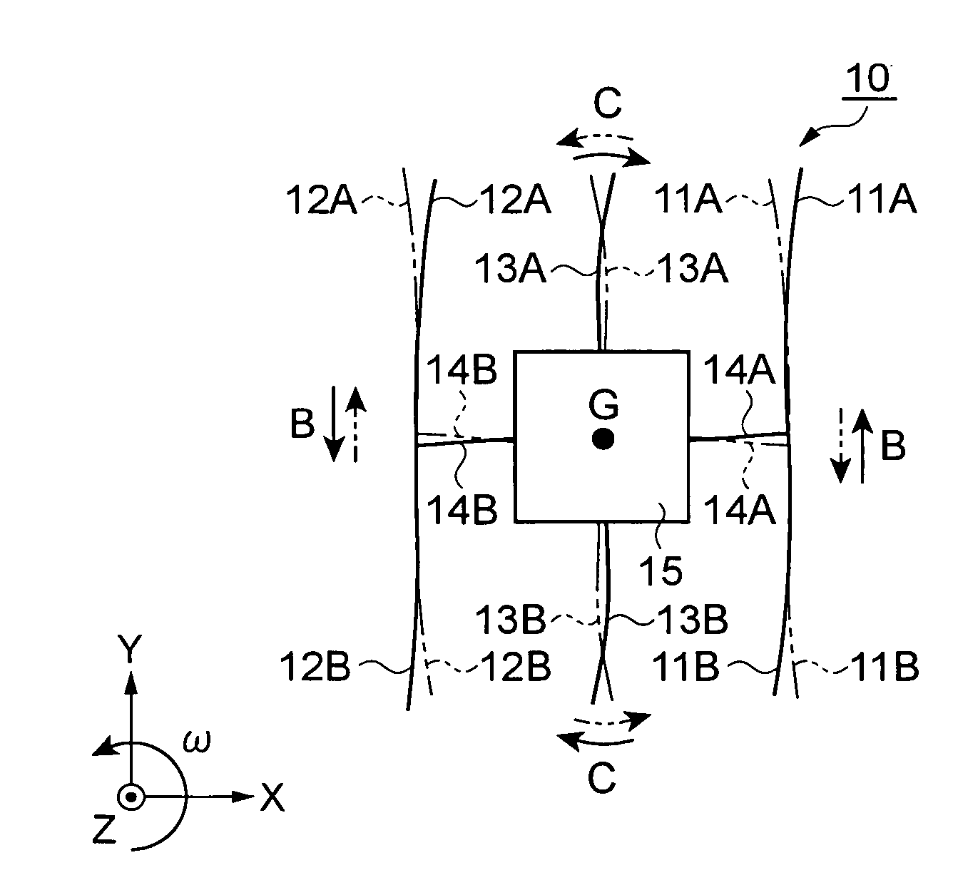
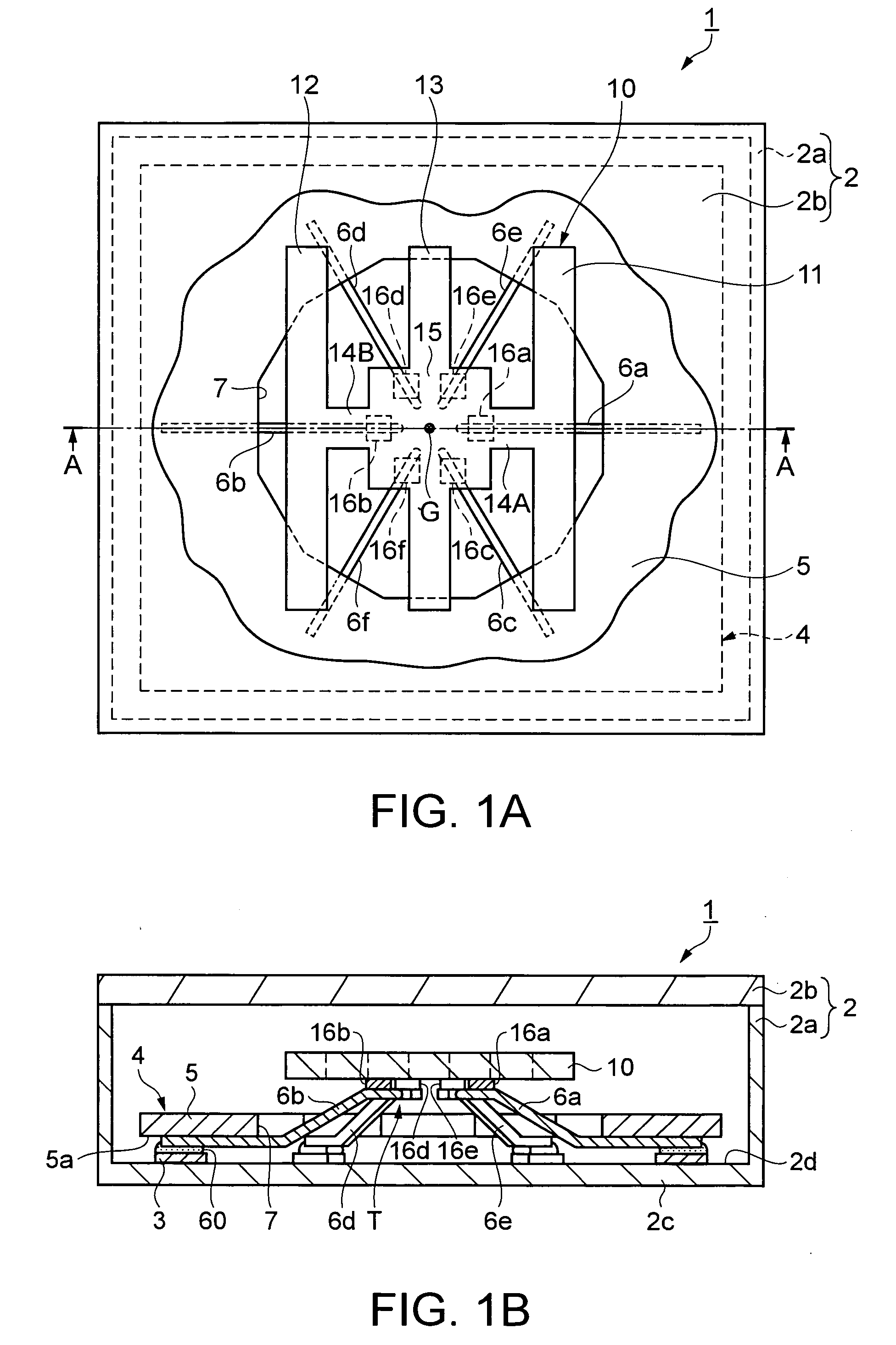
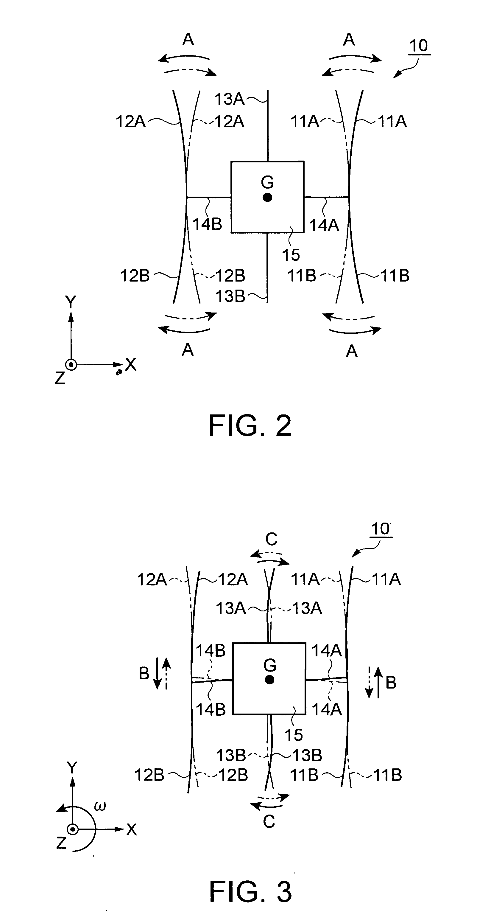
[0030]FIG. 1A is a front view illustrating a gyro sensor and a supporting structure thereof, and FIG. 1B is a cross-sectional view of the gyro sensor taken along line A-A of FIG. 1A. Note that in FIG. 1A, a package lid that covers the gyro sensor is partly cut away for illustration thereof.

[0031] Gyro Sensor

[0032] First, an overall structure of a gyro sensor 1 will now be described.

[0033] The gyro sensor 1 includes: a gyro vibration piece 10 as a piezoelectric vibration gyro vibrator made of quartz; a plurality of (six in this embodiment) electrode leads 6a to 6f that serve to support and are electrically connected to the gyro vibration piece 10; a supporting substrate 4 having a base 5 that serves to support one end of each of the electrode leads 6a to 6f; a package body 2a, which is a ...

second embodiment

[0077] In the above-described first embodiment, the supporting structure for the gyro vibration piece 10 and the gyro sensor 1 achieved thereby have been described. The invention is not limited to them. It is possible to provide electronic devices containing the gyro sensor 1, such as a digital still camera 200 as illustrated in FIG. 7, a camera-equipped mobile phone 300 as illustrated in FIG. 8, and the like.

[0078]FIG. 7 is a schematic perspective view illustrating a structure of the digital still camera. FIG. 8 is a schematic perspective view illustrating a structure of the camera-equipped mobile phone.

[0079] In FIG. 7, the digital still camera 200 has a display panel 204, such as a liquid crystal display, provided on a rear side of a main body case 201. In addition, a photodetector 202 including an optical lens, a charge coupled device (CCD), etc., is provided on an observation side (i.e., on a hidden side, in the figure) of the main body case 201 of the digital still camera 20...


PUM


Abstract

A piezoelectric vibration gyro sensor includes: a) a piezoelectric vibration gyro element including: a central supporting portion having a plurality of electrode terminals provided thereon; a detection arm extending from two opposing sides of the central supporting portion and on a symmetry axis that passes through a center of the central supporting portion; a pair of connection arms extending from other opposing sides of the central supporting portion and in a direction orthogonal to the detection arm; and a pair of drive arms each extending from a tip of one of the pair of connection arms orthogonally to the respective connection arm and to both sides so that the pair of drive arms are symmetrically arranged with respect to the symmetry axis, wherein the central supporting portion, the detection arm, the pair of connection arms, and the pair of drive arms lie in a common plane; and b) a supporting substrate having a plurality of electrode leads one end of each of which is connected to a corresponding one of the plurality of electrode terminals to support the piezoelectric vibration gyro element, wherein the plurality of electrode terminals are disposed on a virtual circle whose center is a center of gravity of the piezoelectric vibration gyro element so as to be symmetrical with respect to the center of gravity, and wherein the plurality of electrode leads are each extended on an extension line that passes from the center of gravity through a central point of a corresponding one of the plurality of electrode terminals.

Description

BACKGROUND [0001] 1. Technical Field [0002] The present invention relates to a piezoelectric vibration gyro sensor including a piezoelectric vibration gyro element to be transversely disposed, and to an electronic device including the piezoelectric vibration gyro sensor. [0003] 2. Related Art [0004] In recent years, as vehicle body control and car navigation systems for vehicles, digital cameras, and digital video cameras are becoming increasingly sophisticated in functionality, there is an increasing demand for improvement of a position control function and a vibration control compensation function of such electronic devices as well as for miniaturization thereof. In such a situation, a piezoelectric vibration gyro sensor (hereinafter referred to as a “gyro sensor”) that includes a so-called transversely-disposed piezoelectric vibration gyro element (hereinafter referred to as a “gyro vibration piece”) is attracting attention. Using the gyro vibration piece made of piezoelectric mo...

Claims


Application Information

Patent Timeline
Patent Type & Authority Applications(United States)
IPC IPC(8): G01P15/08G01C19/56G01C19/5628
CPCG01C19/5607
Inventor SATO, KENJI
Owner SEIKO EPSON CORP
Why Eureka
Try Eureka