

Seal ring holder for membrane element and membrane element
a membrane element and ring holder technology, applied in the direction of mechanical equipment, separation processes, filtration separation, etc., can solve the problems of limited diameter of wound structure b>2/b> and limited increase of membrane area, and achieve the effect of increasing the area of membranes packed
Inactive Publication Date: 2007-01-25
NITTO DENKO CORP
View PDF5 Cites 10 Cited by
- Summary
- Abstract
- Description
- Claims
- Application Information
AI Technical Summary
Benefits of technology
The present invention provides a seal ring holder for membrane elements that can increase the area of membranes packed per element by holding a larger number of membrane elements in a spiral wound membrane element. The seal ring holder has a first ring part, a projecting ring part, a second ring part, and a third ring part. The first ring part is inserted into the membrane element and holds a seal ring, while the second and third ring parts hold the membrane element and allow for a seal ring to be fitted. The third ring part has a smaller outer diameter than the projecting ring part, which increases the space between them. This allows for better performance of the seal ring in receiving and spreading the raw liquid. The membrane element using the seal ring holder has a larger area of membranes packed per element.
Problems solved by technology
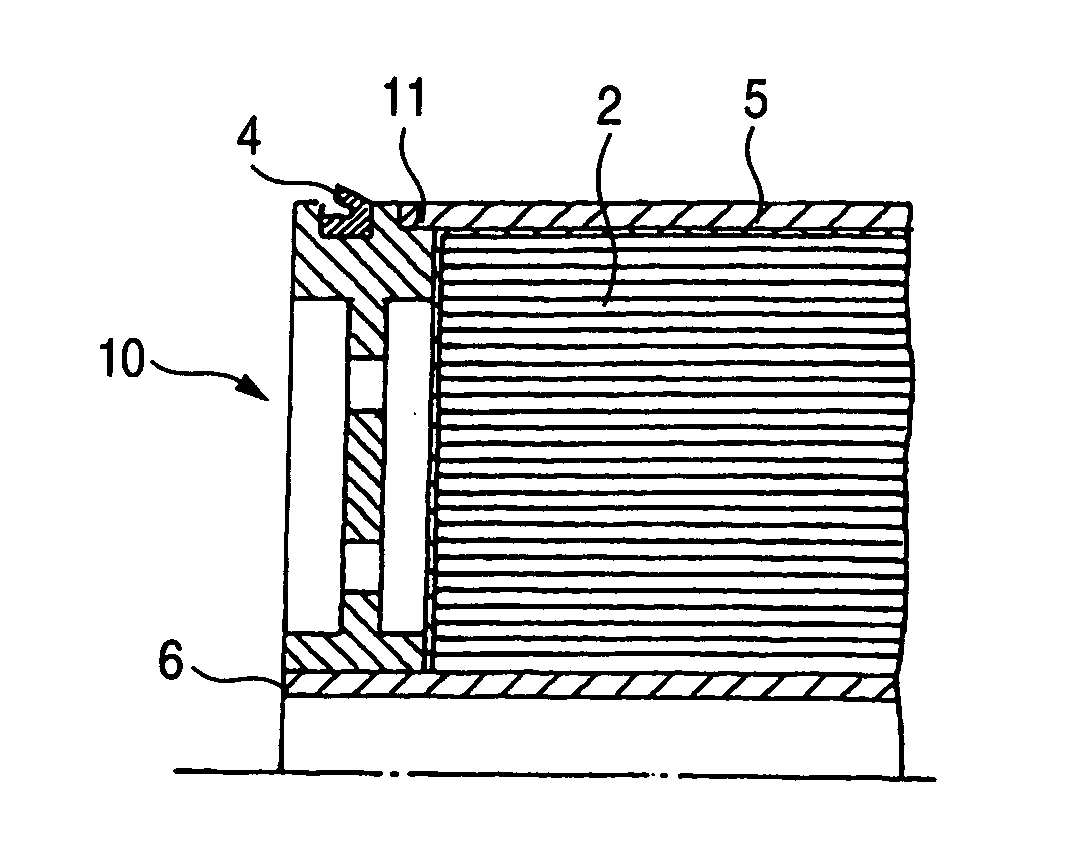
However, the structure in which the wound structure 2 is inserted into the cylindrical part 19 has had a drawback that the diameter of the wound structure 2 is limited and, hence, to increase the membrane area is limited.
Method used
View moreImage
Smart ImageViewing Examples

Examples
example 1
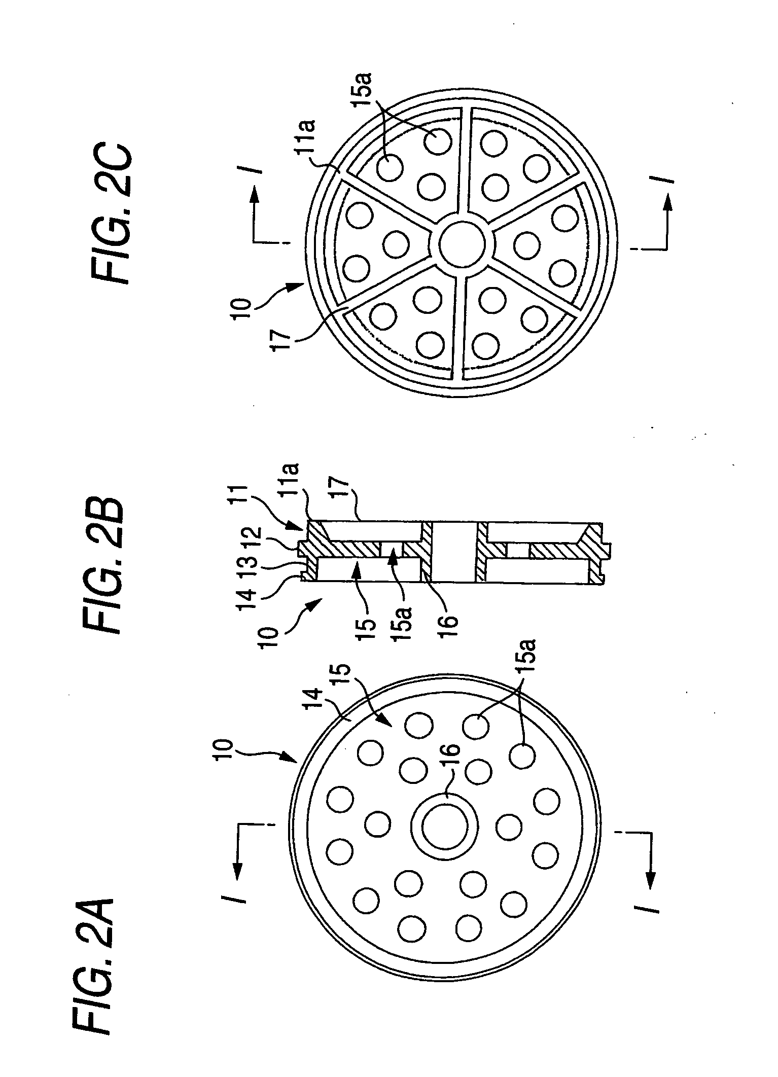
[0070] A seal ring holder having the structure shown in FIG. 2 was produced. This seal ring holder had no skirt and had the following dimensions. Overall thickness (same as the thickness from the surface for butt joint with wound-structure end face): 20 mm, bonding allowance for sheathing member: 6 mm, width of seal ring groove: 8 mm, depth of seal ring groove: 6.5 mm, upstream-side wall height of seal ring groove: 3.5 mm.
Login to View More PUM
| Property | Measurement | Unit |
|---|---|---|
| widths | aaaaa | aaaaa |
| widths | aaaaa | aaaaa |
| widths | aaaaa | aaaaa |
Abstract
A seal ring holder for membrane elements which is capable of attaining an increase in the area of membranes packed per element; and a membrane element using the seal ring holder, are provided. The seal ring holder for membrane elements which is disposed at an end part of a spiral wound membrane element to hold a ring seal ring on the outer periphery thereof while allowing a raw liquid to flow into a membrane end part of the membrane element, includes: a first ring part which has a side wall facing an upstream-side membrane end part of the membrane element and is inserted into an end part of a sheathing member of the membrane element; a projecting ring part which has been formed upstream from the first ring part and has side walls respectively on both sides, an edge face of the sheathing member and the downstream-side edge face of the seal ring being fixable respectively to the side walls; a second ring part which is formed upstream from the projecting ring part and to the outer periphery of which the seal ring is to be fitted; and a third ring part which is formed upstream from the second ring part and to which the upstream-side end face of the seal ring is fixable.
Description
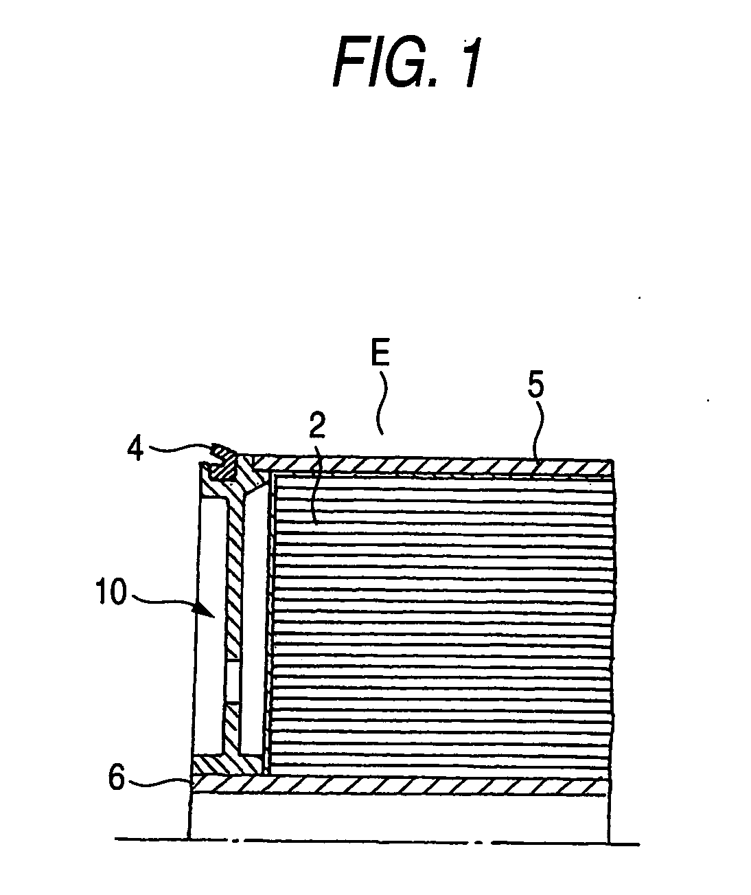
FIELD OF THE INVENTION [0001] The present invention relates to a seal ring holder which holds a seal ring for closing the space between a spiral wound membrane element and a vessel, and a membrane element using the seal ring holder. More particularly, the present invention relates to a seal ring holder with which a membrane element can have a larger amount of a membrane part (membrane leaves) packed therein than before, and a membrane element. DESCRIPTION OF THE RELATED ART [0002] Spiral wound separation membrane modules have hitherto been used in a wide range of applications such as the desalting of brine or seawater, production of ultrapure water, and wastewater treatments. As shown in FIG. 6, spiral wound separation membrane modules have a structure which comprises a pressure vessel 1 and a spiral wound separation membrane element E housed therein and in which the space between the vessel 1 and the element E has been closed with a ring seal ring 4 so that a raw liquid 7 supplied ...
Claims
Login to View More Application Information
Patent Timeline
 Patent Type & AuthorityApplications(United States)
IPC IPC(8): B01D63/00B01D63/10B01D65/00F16J15/02
CPCB01D65/003B01D63/10Y02A20/131B01D2313/041B01D2313/06
InventorCHIKURA, SHINICHIUDA, YASUHIRO
OwnerNITTO DENKO CORP