
Area-Efficient Capacitor-Free Low-Dropout Regulator

a capacitor-free, area-efficient technology, applied in the direction of electric variable regulation, process and machine control, instruments, etc., can solve the problems of significant increase in chip area and cost, unstable ldo regulator of fig. 1, and ineffective solution, so as to improve both frequency and dynamic response, improve stability of regulator, and sacrifice performance

Active Publication Date: 2007-01-25
THE HONG KONG UNIV OF SCI & TECH
View PDF5 Cites 45 Cited by
  • Summary
  • Abstract
  • Description
  • Claims
  • Application Information

AI Technical Summary

Benefits of technology

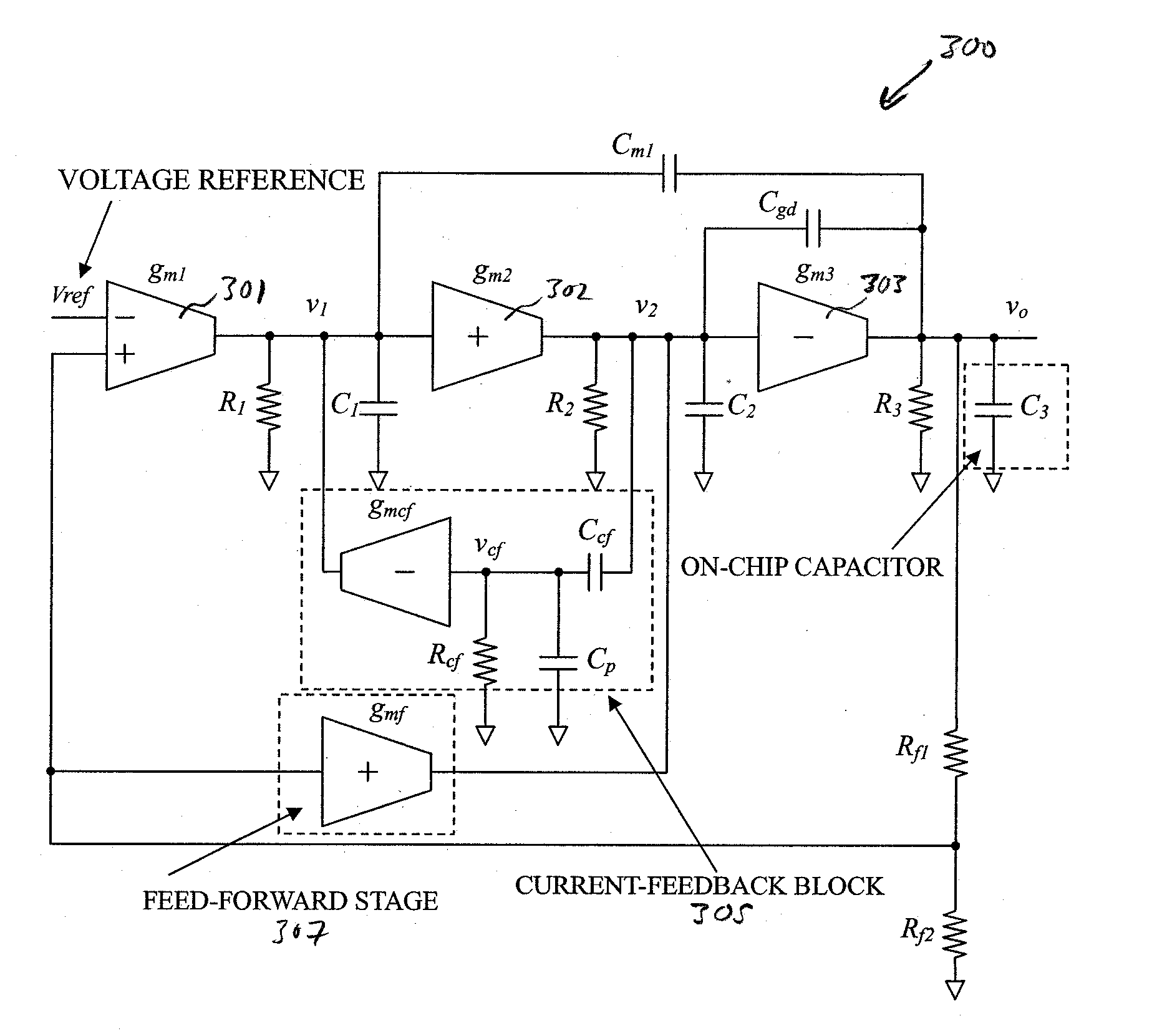
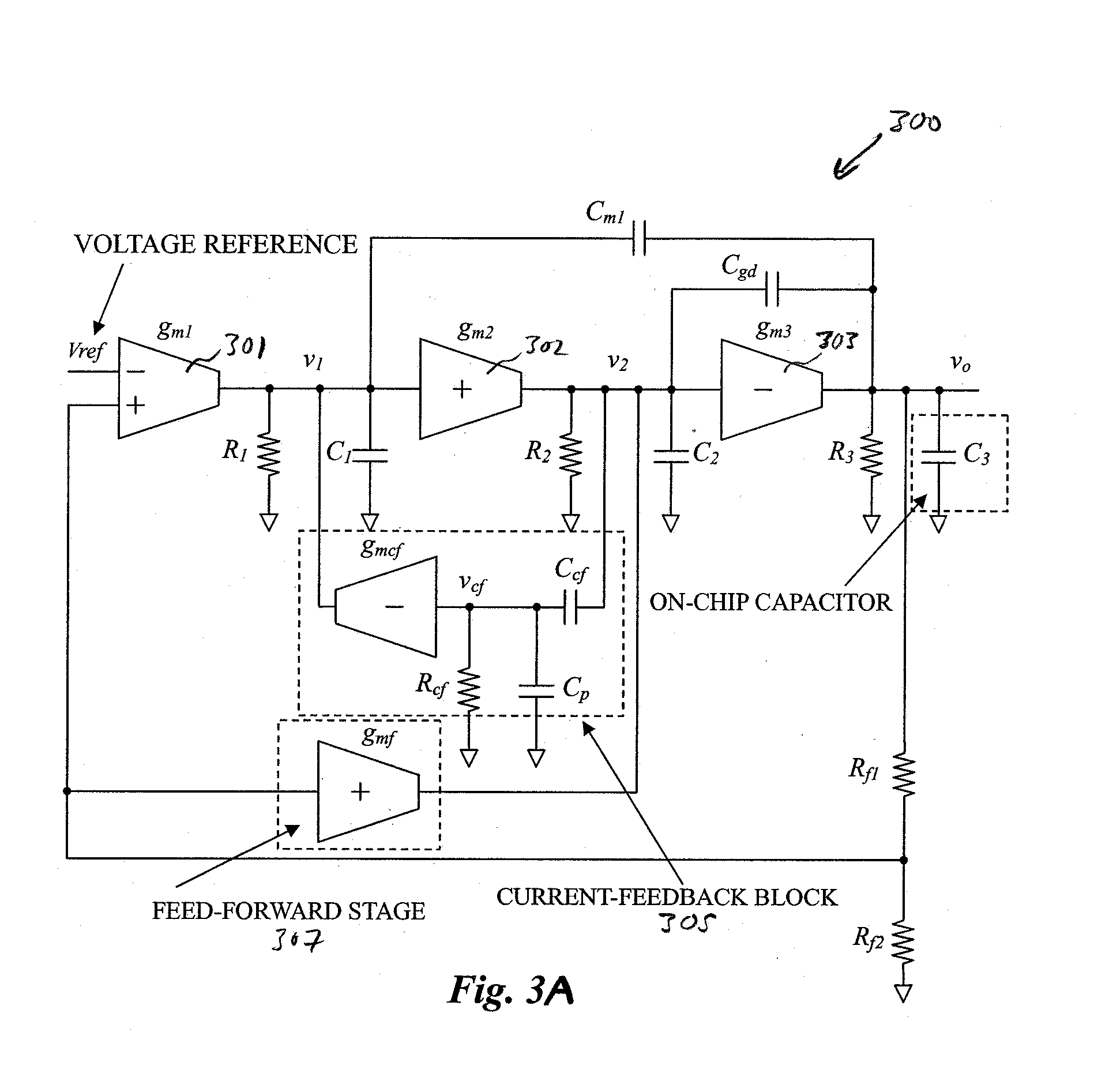
[0006] According to the present invention, there is provided a three-stage capacitor-free low-dropout regulator comprising: first, second and third gain stages wherein said first gain stage having a differential input stage and a single-ended output, a high-swing second gain stage with input connecting to the output of the first stage and a single-ended output, a power PMOS transistor as the third gain stage with gate terminal connecting to the output of the second stage, source terminal connecting to the input voltage, and drain terminal connecting to the output of the regulator. A capacitor is connected between the output of the first stage and the output of the regulator while a voltage reference is connected to the negative of the error amplifier. A current feedback block is for feeding back a small-signal current that is proportional to the time derivative of the output voltage of the second stage to the output of the first stage. It can control the damping factor of the second and third complex poles of the said regulator so as to improve the stability of the regulator without using a large compensation capacitor Cml and sacrificing the performance.
[0007] The regulator may preferably be provided with a feedforward transconductance stage extending from the output of the first stage to the output of the regulator to further improve both frequency and dynamic responses.

Problems solved by technology

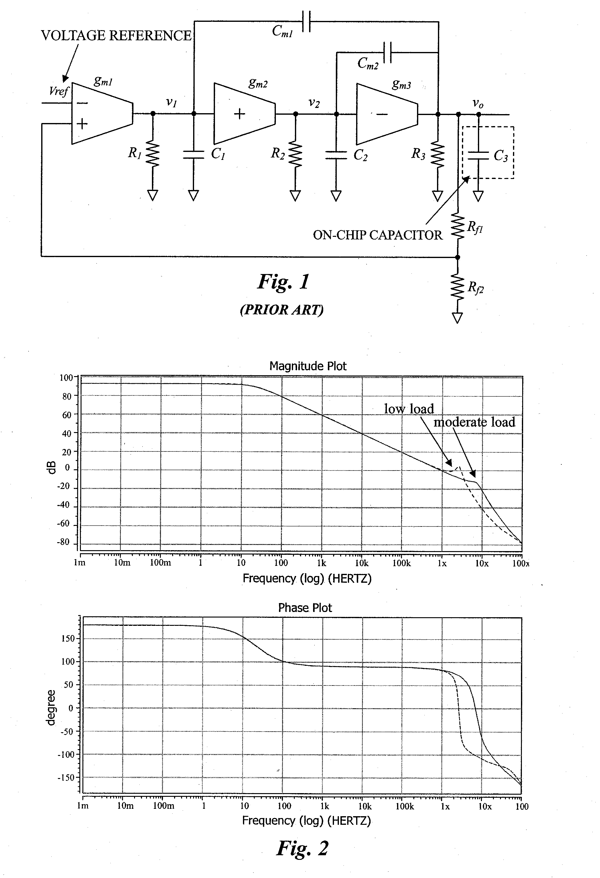
The LDO regulator of FIG. 1 suffers from stability problems especially when the load current is below several milli-amperes.
However, this is not an effective solution as the frequency response and transient performance are sacrificed.
In addition, both chip area and cost are increased significantly.

Method used


Image

  • Area-Efficient Capacitor-Free Low-Dropout Regulator
  • Area-Efficient Capacitor-Free Low-Dropout Regulator
  • Area-Efficient Capacitor-Free Low-Dropout Regulator

Examples


Embodiment Construction

[0020] Referring to FIG. 3A there is shown schematically the structure of a capacitor-free low-dropout regulator 300 according to a preferred embodiment of the invention. The capacitor-free LDO regulator comprises of three gain stages. The first gain stage 301 is a high-gain error amplifier having a differential input and single-ended output gain stage with transconductance gm1, where the inverting terminal is connected to the output of the voltage reference while the non-inverting terminal is connected to a feedback resistor Rf1, and has an output resistance R1 and a parasitic capacitance C1. A second stage 302 receives the output signal of the first stage 301 and is a positive gain stage with transconductance gm2, output resistance R2 and parasitic capacitance C2. A third gain stage 303 receives the output signal of second stage 302 and is a negative gain stage with transconductance gm3 and output resistance R3. In addition, C3 is the on-chip capacitance.

[0021] As there are three...


PUM


Abstract

An area-efficient capacitor-free low-dropout regulator based on a current-feedback frequency compensation technique is disclosed. An implementation of a current feedback block with a single compensation capacitor is used to enable capacitance reduction. The resultant low-dropout regulator does not generally require an off-chip capacitor for stability and is particularly useful for system-on-chip applications.

Description

CROSS-REFERENCE TO RELATED APPLICATION [0001] This application claims the benefit of U.S. Provisional Application No. 60 / 701,373, filed Jul. 22, 2005, entitled “Chip-Area-Efficient Capacitor-Free Low-Dropout Regulator,” which application is incorporated in its entirety by reference as if fully set forth herein.FIELD OF THE INVENTION [0002] This invention relates to frequency compensation technique for low-voltage capacitor-free low-dropout regulators, in particular to such regulators which do not require an off-chip capacitor for stability, and to low-dropout regulators or amplifiers incorporating such techniques. BACKGROUND OF THE INVENTION [0003] Conventionally, an off-chip output capacitor is required for achieving low-dropout regulator (LDO) stability, as well as good line and load regulations. However, the off-chip capacitor is the main obstacle to fully integrating the LDO in system-on-chip (SoC) applications. With the recent rapid development of SoC designs, there is a growin...

Claims


Application Information

Patent Timeline
Patent Type & Authority Applications(United States)
IPC IPC(8): G05F1/00
CPCG05F1/575
Inventor MOK, KWOK TAILAU, SAILEUNG, KA
Owner THE HONG KONG UNIV OF SCI & TECH
Learn More