Magnetic sensor

Active Publication Date: 2007-01-25
DENSO CORP
View PDF1 Cites 57 Cited by
  • Summary
  • Abstract
  • Description
  • Claims
  • Application Information

AI Technical Summary

Benefits of technology

[0008] The present invention was developed in view of the aforementioned problems. It is therefore an object of the present invention to provide a magnetic sensor tha

Problems solved by technology

However, the conventional technique shown in FIG. 10A provides the bias magnet 55 outside the molded package, raising a problem that the magnetic sensor 50 is increased in size by the dimensions of the bias magnet 55.
In aligning and bonding the bias magnet 55 using the adhesive material 54

Method used


Image

  • Magnetic sensor
  • Magnetic sensor
  • Magnetic sensor

Examples


Example

First Embodiment

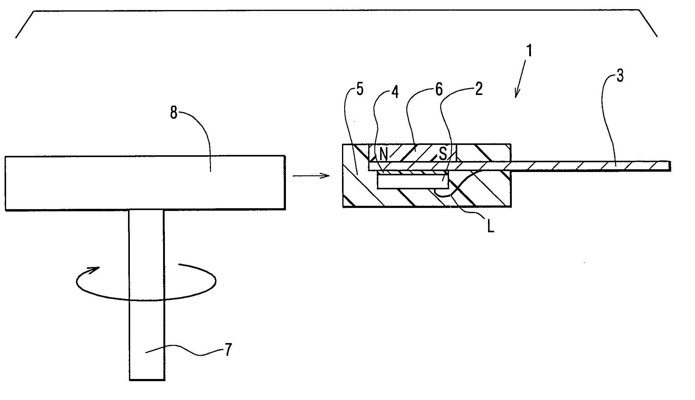
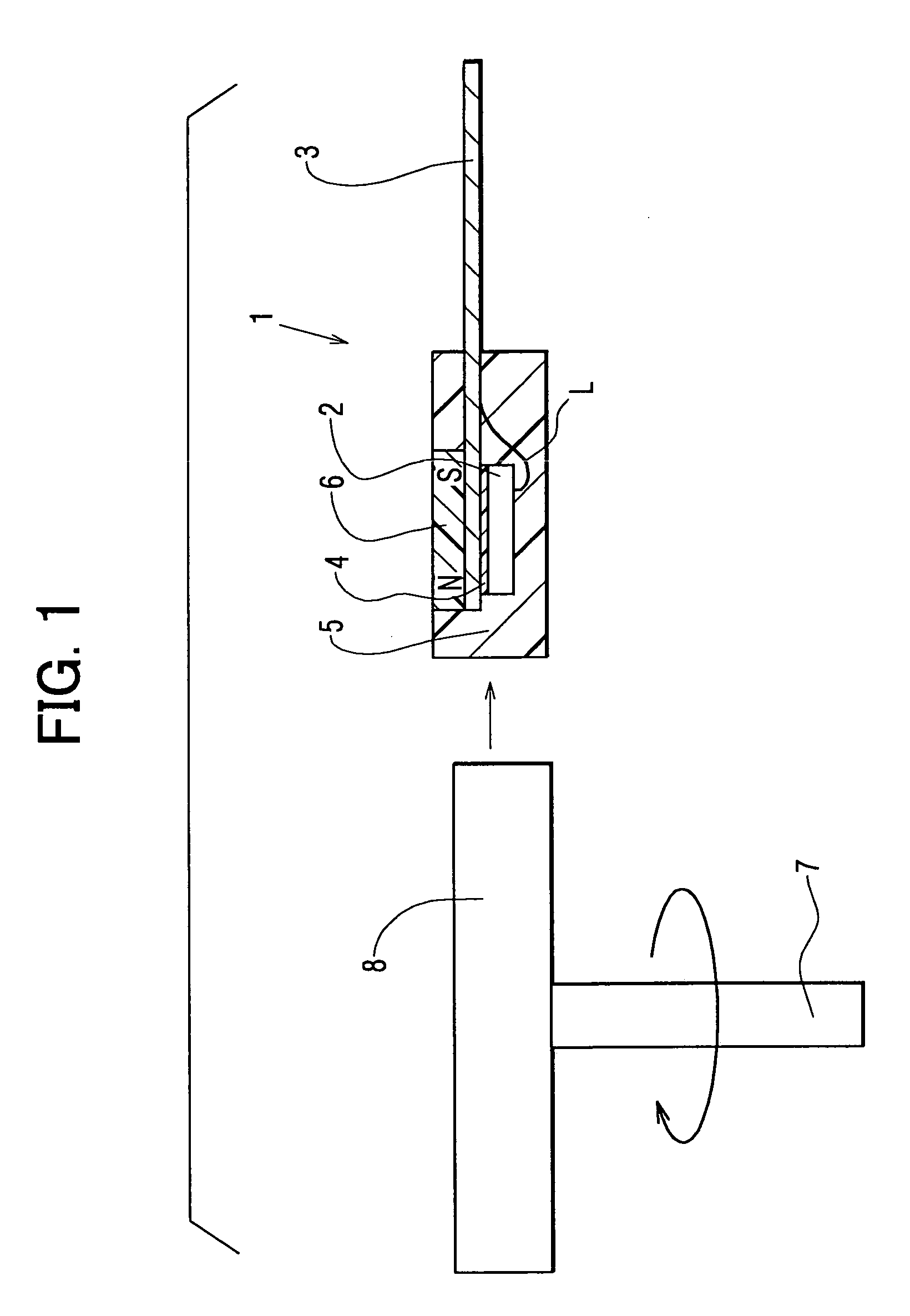
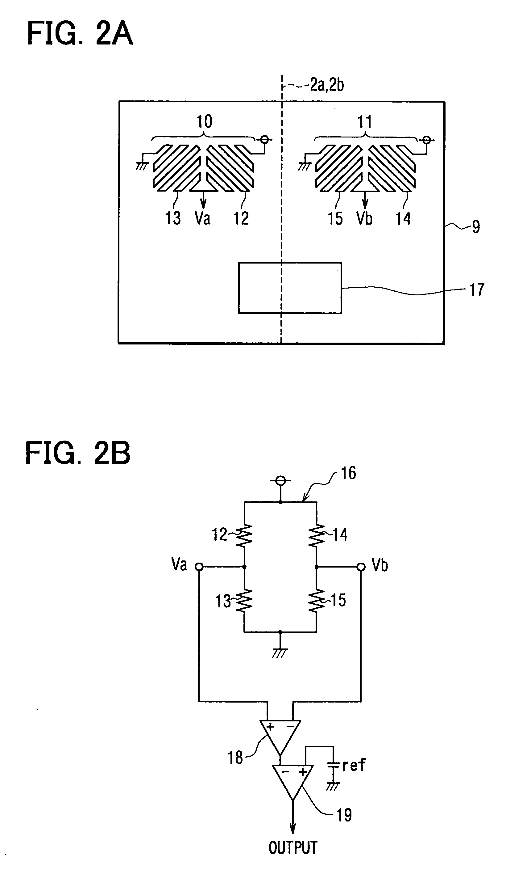
[0036] Now, the present invention will be described with reference to the accompanying drawings in accordance with a magnetic sensor according to a first embodiment. FIG. 1 is a cross-sectional view of a magnetic sensor and a magnetic rotor (an object to be detected) according to the first embodiment of the present invention. FIG. 2A is a plan view of the magnetic sensor chip according to the first embodiment of the present invention, while FIG. 2B is a circuit diagram of the circuit configuration of a magnetoresistive pattern according to the first embodiment of the present invention.

[0037] This embodiment provides a magnetic sensor 1 which can be employed as a rotation detector, for detecting the rotation of a rotating object (including gears) to be sensed, such as an engine rotation sensor, a cam angle sensor, a crank angle sensor, an automobile speed sensor, an AT sensor, and a wheel speed sensor. Referring to FIG. 1, on the right hand side of a gear-shaped (it...

Example

Second Embodiment

[0055] Now, the present invention will be explained with reference to FIG. 6 in accordance with a second embodiment. The portions of the second embodiment common to those of the first embodiment are not to be explained in detail. This embodiment is different from the first embodiment in that the bias magnet 6 is formed at a portion on a side of the magnetic sensor chip 2.

[0056] A method according to this embodiment makes use of the property that a magnetic material is less magnetized when its Curie temperature is reached, thereby being readily affected externally. To reach the Curie temperature, the lead frame 3 is provided with a heat-generating portion, which is part of the lead frame 3 reduced in shape to have an increased resistance and generates heat by a large current flowing therethrough. This heat-generating portion is formed, within the lead frame 3, near the optimal position at which the aforementioned bias magnet 6 is desirably formed.

[0057] First, as ...

Example

Third Embodiment

[0059] Now, the present invention is explained with reference to FIG. 7 in accordance with a third embodiment. The portions of the third embodiment common to those of the aforementioned embodiments will not be explained in detail. This embodiment is different from the aforementioned embodiments in that the bias magnet 6 is formed in the lead frame 3.

[0060] A method according to this embodiment includes the step of using a magnetized yoke to magnetize the optimal position desired to form the aforementioned bias magnet 6 in the lead frame 3 made of known copper or 42Ni—Fe or the like, thereby forming the bias magnet 6. In this manner, the lead frame 3 is employed as the bias magnet 6. Thus, a conventionally available lead frame 3 can be used to form the bias magnet 6 without mixing magnetic powder into the molded material 5, thereby facilitating manufacture.


PUM


Abstract

The magnetic sensor is fabricated such that a magnetic sensor chip, having a one-chip structure in which MRE bridges and a comparator are included, is mounted onto a lead frame using an adhesive material, and then the magnetic sensor chip mounted on the lead frame is encapsulated by molding in a molded material. The magnetic sensor includes a magnetic-field generating portion formed by magnetizing at least one of the chip mounting member, the adhesive material, and the encapsulating material.

Description

CROSS REFERENCE TO RELATED APPLICATIONS [0001] This application is based upon, claims the benefit of priority of, and incorporates by reference Japanese Patent Application No. 2003-55823 filed Mar. 3, 2003. BACKGROUND OF THE INVENTION [0002] 1. Field of the Invention [0003] The present invention relates to a magnetic sensor, and more particularly, to a magnetic sensor that is employed as a rotation sensor for providing control to an automobile engine or ABS control in an automobile brake system. [0004] 2. Description of the Related Art [0005]FIG. 10A is a cross-sectional view of the configuration of a magnetic sensor disclosed in Japanese Patent Laid-Open Publication No. Hei 9-79865 (1997), while FIG. 10B is a cross-sectional view of a modified example of FIG. 10A. As shown in FIG. 10A, a magnetic sensor 50 is fabricated in a manner such that a magnetic sensor chip 51 having a magneto-resistance element (MRE) and mounted on a lead frame 52 is packaged by molding in a molded material...

Claims


Application Information

Patent Timeline
IPC IPC(8): G01R33/02F02D35/00G01B7/30G01D5/14G01D5/16G01D5/20G01D5/245G01D5/249G01D11/24G01P3/488G01R33/06G01R33/09H01L23/28
CPCG01D5/145G01D11/245H01L2924/13091H01L2924/1305H01L2224/73265H01L2224/32245H01L2224/48091H01L2224/48247Y10T29/49002H01L2924/00014H01L2924/00H01L24/73H01L2924/181H01L2924/00012G01D5/245
Inventor AO, KENICHI
Owner DENSO CORP
Why Eureka
Try Eureka