Optical connector-use adaptor and optical connector use shutter component

a technology of optical connectors and shutter components, applied in the field of optical connector adapters, can solve the problems of increased manufacturing costs, increased material costs, and leaking laser beams, and achieve the effect of reducing manufacturing costs and material costs and ensuring satisfactory optical transmission

Inactive Publication Date: 2007-01-25
FURUKAWA TECHNO MATERIAL
View PDF2 Cites 15 Cited by
  • Summary
  • Abstract
  • Description
  • Claims
  • Application Information

AI Technical Summary

Benefits of technology

[0010] An object of the present invention is to provide an optical connector adapter and a shutter component for optical connection, which may hold down a manufacturing

Problems solved by technology

The leaking laser beam is liable to harm the eyes or others of an operator engaged in connection works.
However, the shutter member 2a requires, at the time when manufacturing the shutter member, the shape memory heat-treatment given with the cut rolled plate constrained in the bent shape, or the bending of the cut rolled plate at a high temperature after the plate-shape memory heat-treatment as described the above, leading to an increase in manuf

Method used


Image

  • Optical connector-use adaptor and optical connector use shutter component
  • Optical connector-use adaptor and optical connector use shutter component
  • Optical connector-use adaptor and optical connector use shutter component

Examples


first embodiment

of Shutter Component for Optical Connection

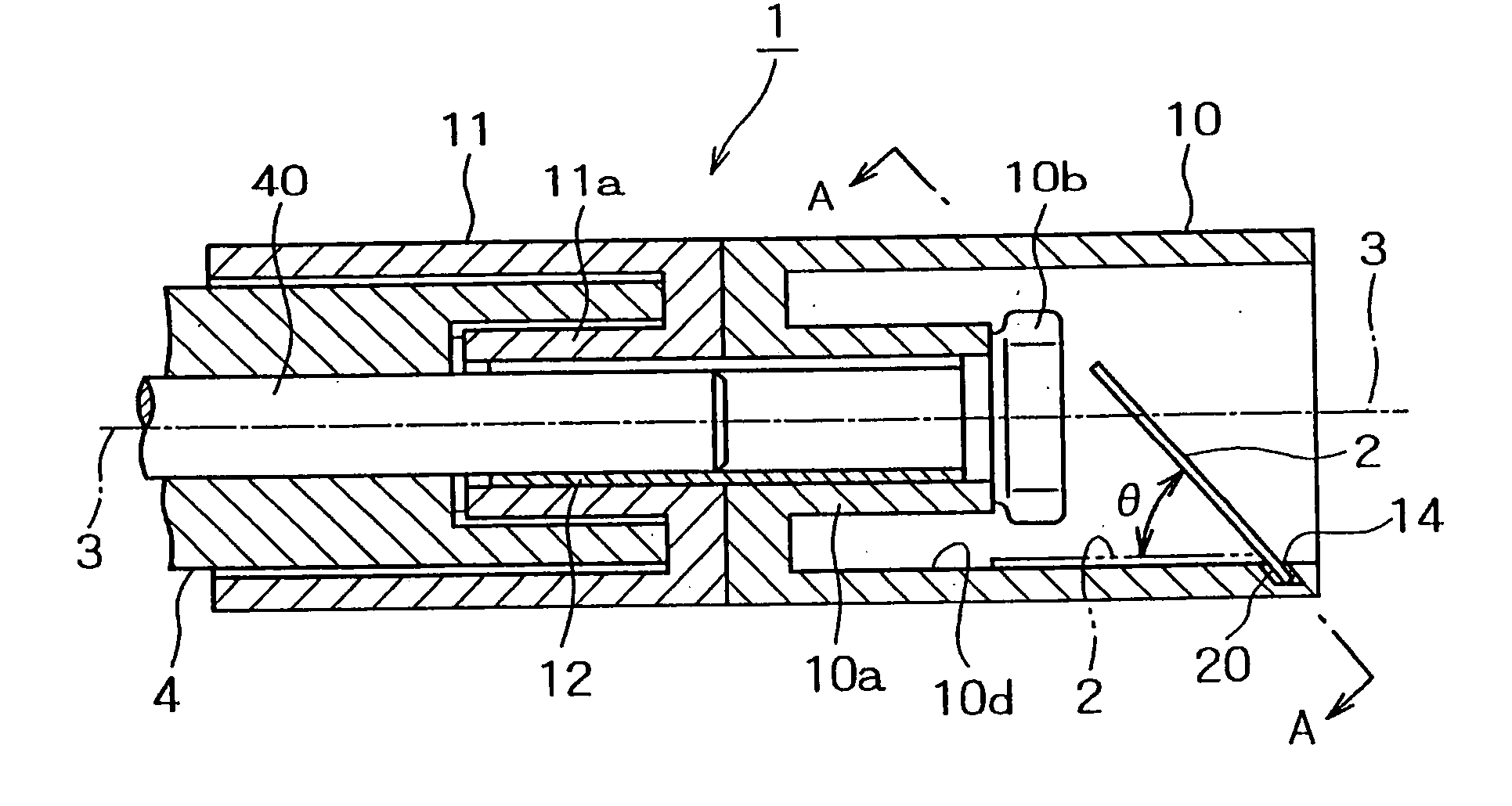
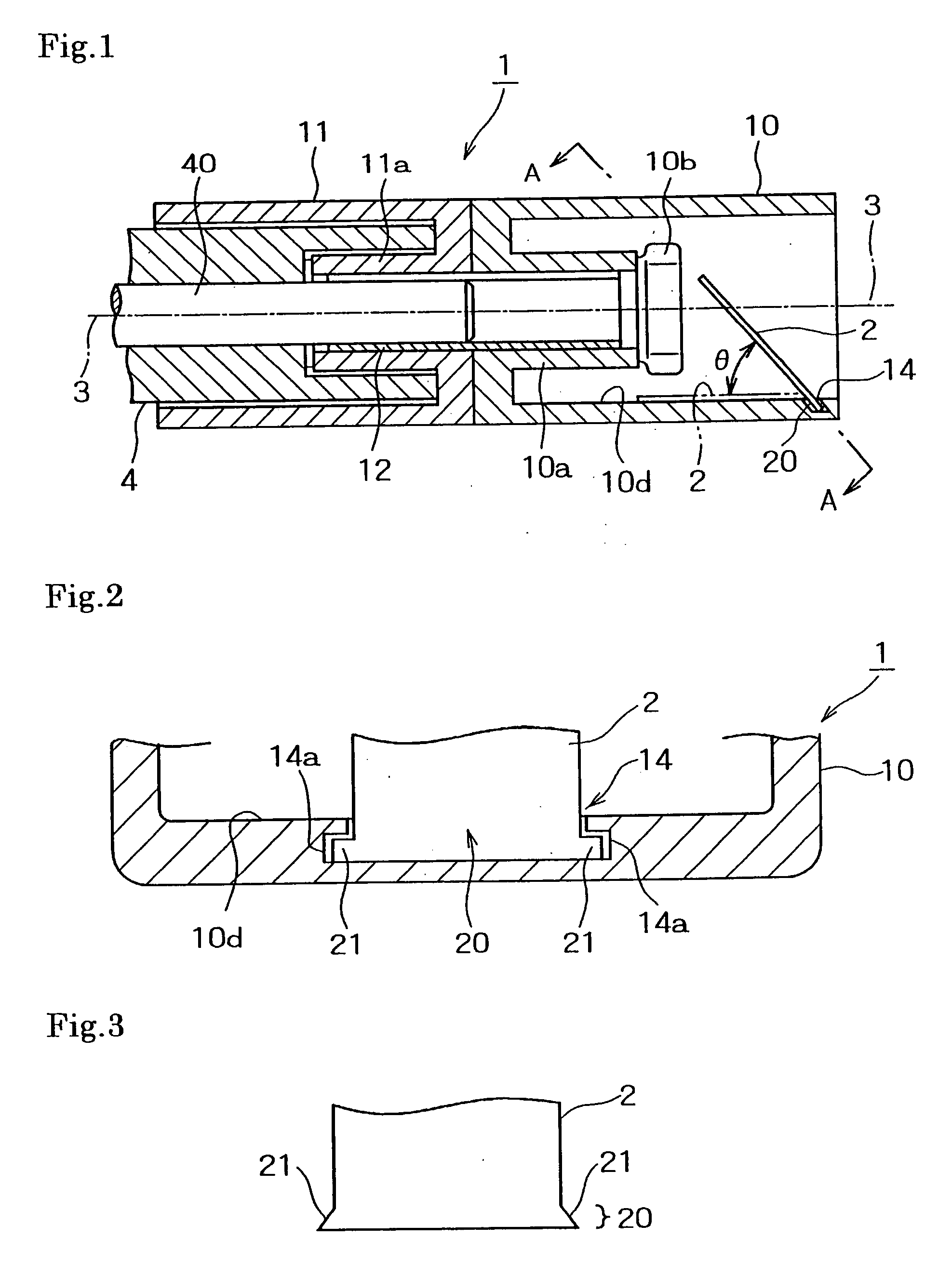
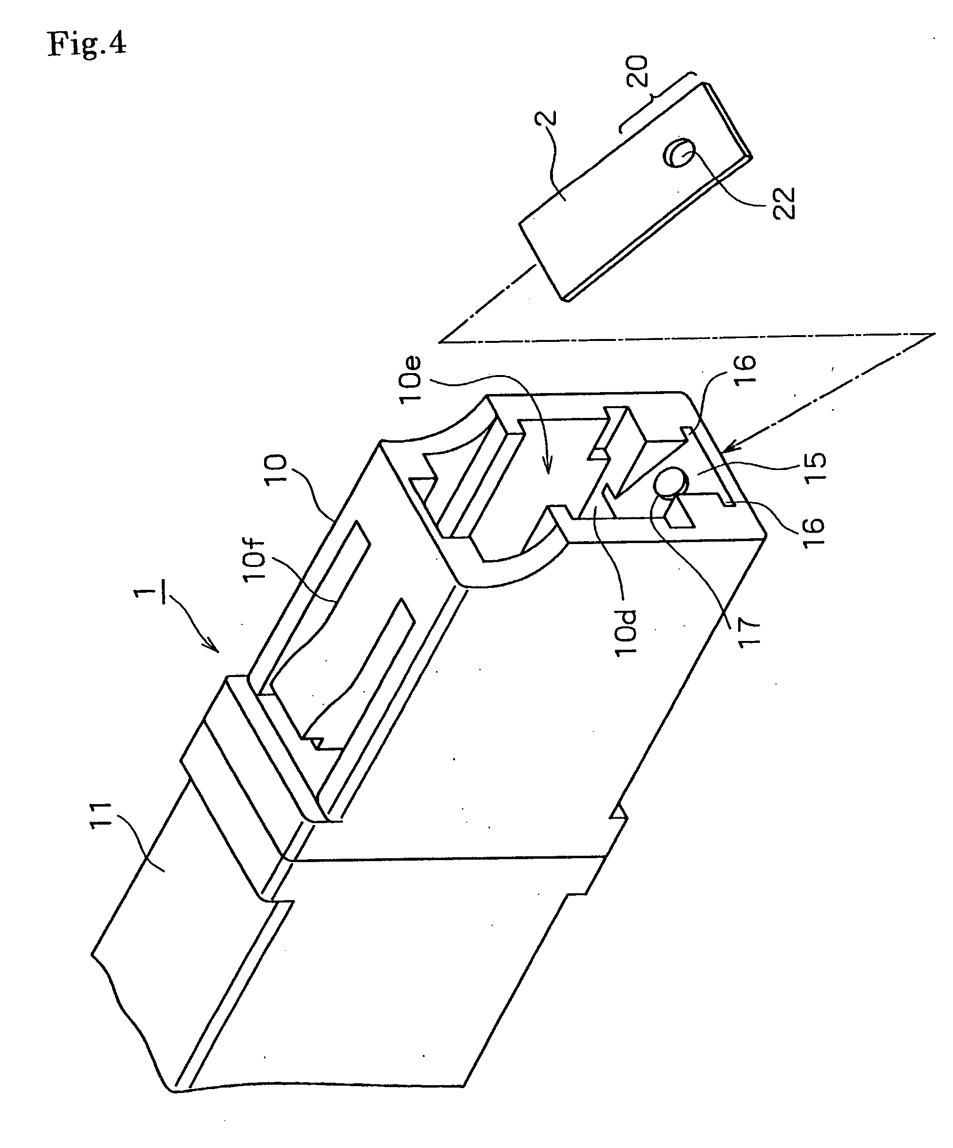
[0040]FIG. 5 shows a shutter component for optical connection of a first embodiment according to the present invention.

[0041] The optical connector adapter 1 is approximately the same in basic configuration as the optical connector adapter of the first embodiment, and like reference numerals are given to like portions, and a detailed description thereof is omitted.

[0042] In the housing part 10 of the connector 1, reference numeral 10g denotes a guide slit serving to guide a projection 61c formed, as a mark of an appropriate insertion position, at an outer circumference of a coupled part 61 in a shutter member 6 described later.

[0043] The shutter component 6 for optical connection has, at one end side, a housing 60 having a tip end being open and adapted to provide coupling with the optical connector 5 by insertion, and at the other end side, the coupled part 61 coupled with the housing part 10 of the optical connector adapter 1 by insert...

second embodiment

of Shutter Component for Optical Connection

[0050]FIG. 6 shows the shutter component for optical connection of the second embodiment according to the present invention.

[0051] In the second embodiment, the optical connector adapter 1 is the same in basic configuration as the optical connector adapter in FIG. 5, so that like reference numerals as shown in the adapter of FIG. 5 are given to like portions, and a description thereof is omitted.

[0052] The shutter component 6 for optical connection has a cylindrical housing 60 mounted to the outer circumference of the housing part 10 of the adapter 1 such that the opening end of the housing part 10 is merged into the housing by a prescribed distance, and the housing 60 has, on left and right surfaces at the outer circumference, flanges (not shown) serving to mount the shutter component to a non-illustrated other member.

[0053] The thin super-elastic alloy shutter plate 2 having been subjected to the plate-shape memory heat-treatment witho...

third embodiment

of Shutter Component for Optical Connection

[0057]FIG. 7 shows the shutter component for optical connection of a third embodiment according to the present invention.

[0058] The shutter component 6 for optical connection is approximately the same in basic configuration as the shutter component 6 of the second embodiment, in which case, however, there is a difference in mounting procedure of the shutter plate 2 between the shutter components 6 in the second and the third embodiments.

[0059] The rectangular shutter plate 2 is mounted to one wall surface 60c within the housing 60 according to the approximately same procedure as that shown in FIG. 4.

[0060] That is, one wall surface 60c in the housing 60 provides, at a position facing the housing part 10 with the housing 60 mounted to the housing part 10 of the adapter 1, a slant surface 65 inwardly slanted toward the opening end of the housing part 10. The slant surface 65 has, thereon, a projection 67 of small height, and at the opposit...


PUM


Abstract

The present invention relates to an optical connector adapter that is so configured as to prevent a laser beam from leaking outwards to do harm to a person at the time of insertion or removal of an optical connector plug for optical connection, and, specifically, an optical connector adapter having, at one end side, a housing part with a tip end being open, and at the other end side, a coupling part adapted to provide coupling with an optical component, and serving to couple an optical connector plug coupled with the housing part by insertion with the optical component such that an optical axis is aligned, wherein a super-elastic alloy shutter plate having been subjected to a plate-shape memory heat-treatment without providing any bent part is so mounted at an inner position close to an opening end of the housing part as to stand upward from one wall surface to a position adapted to shield the optical axis.

Description

TECHNICAL FIELD [0001] This invention relates to an optical connector adapter serving to prevent a laser beam from leaking outwards at the time when an optical connector plug or like optical component is inserted into or removed from the adapter for connection to or disconnection from an optical fiber, and also, a shutter component for optical connection, which is useful for the same purpose as the above by being mounted to the optical connector adapter. BACKGROUND ART [0002] With an optical connector plug or like optical component coupled with only one end of an optical connector adapter, outward leakage of a laser beam emitted from an optical fiber occurs at the time when the optical component is inserted into or removed from the optical connector adapter. The leaking laser beam is liable to harm the eyes or others of an operator engaged in connection works. Thus, for the purpose of preventing a danger as described the above, an optical connector adapter as shown in FIG. 9 has bee...

Claims


Application Information

Patent Timeline
IPC IPC(8): G02B6/38G02B6/42
CPCG02B6/3825G02B2006/4297G02B6/3849
Inventor IWAI, HIROHISATAKAHASHI, SHINTAROUHABU, TETSUSHITAKAOKA, SATOSHITAKEUCHI, YOSHINORI
Owner FURUKAWA TECHNO MATERIAL
Why Eureka
Try Eureka