Electroluminescent display device and a digital camera using an electroluminescent display device

a technology of electroluminescent display device and display device, which is applied in the field of electroluminescent display device and digital camera, can solve the problems of limiting the size of the monitoring device that can be enlarged without increasing the size of the camera, becoming more and more difficult to frame and display the object image on the monitoring device, and reducing the size of the monitoring device. , the effect of avoiding the size of the monitoring device and reliable activation of the switch

Inactive Publication Date: 2007-01-25
RICOH IMAGING COMPANY
View PDF14 Cites 50 Cited by
  • Summary
  • Abstract
  • Description
  • Claims
  • Application Information

AI Technical Summary

Benefits of technology

[0026] According to the present invention, the user can perceive the activation of the switch via finger contact because a contact of the switch is resiliently deformed to turn the switch ON and OFF when the user activates the switch by pressing a surface of the electroluminescent display, which allows reliable activation of the switch. Moreover, if the camera body is miniaturized, a significant reduction in size of the monitoring device can be avoided, or no reduction in the size of the monitoring device may be necessary at all, which makes it easy for the user to frame the object image while looking through the monitoring device and also makes it easy for the user to visually check the focus of reproduced object images. Furthermore, since various operating switches are made using indications of the monitoring device, the various operating switches can be arranged to be sufficiently spaced from one another, which improves the operability of the various operating switches and makes it possible to largely display of the various operating switches on the monitoring device so as to be easily read.
[0027] Furthermore, according to the present invention, since the right release button and the left release button, which are selectively enabled by changing settings of the release buttons, are provided on right and left portions of the camera body, respectively, photographing is not dependent on the dominant hand of the photographer; moreover, the operability of the camera can be improved even in the case of taking self-portrait pictures while the operability of various operating switches such as mode select switches can be improved. In this case, changing the indication pattern of the monitoring device to correspond to the enabled right or left release button improves the operability of the various operating switches and further allows live images (moving images) and reproduced images to be easily viewed by the monitoring device.

Problems solved by technology

Accordingly, there is a limit to how much the size of the monitoring device can be enlarged without increasing the size of the camera.
Specifically in recent years, it has become more and more difficult to enlarge the display screen size of the monitoring device because miniaturization of the camera has continued to advance.
Therefore, it is difficult to frame and display the object image on the monitoring device and to visually check the focus state of the displayed object image.
Additionally, although various setting screens (e.g., mode setting icons) are indicated on the monitoring device so that a desired mode such as a photographing mode can be selected from among various modes, letters and characters displayed on the monitoring device are so small that they cannot be easily read, and accordingly, the setting operation for the mode selection is difficult.
However, since no object images can be displayed on the input device disclosed in the Japanese unexamined patent publication No. 2005-63413, there is still no monitoring device that can be arranged on at least the area in which the input device is arranged.
Moreover, it is difficult to enlarge the area of the monitoring device over the entire back surface of the camera to enlarge the monitoring device while achieving miniaturization of the camera.
In addition, when the photographer (user) touches a surface of the touch panel by their finger to actuate a switch on the touch panel, the photographer cannot feel a tactile “click,” response from the touch panel, and accordingly, the photographer cannot perceive the activation of the switch through their finger, and sometimes the switch is not activated due to an inadequate contact, which may have an adverse effect on the photographer's confidence in achieving a desired photographing operation.

Method used


Image

  • Electroluminescent display device and a digital camera using an electroluminescent display device
  • Electroluminescent display device and a digital camera using an electroluminescent display device
  • Electroluminescent display device and a digital camera using an electroluminescent display device

Examples


first embodiment

[First Embodiment]

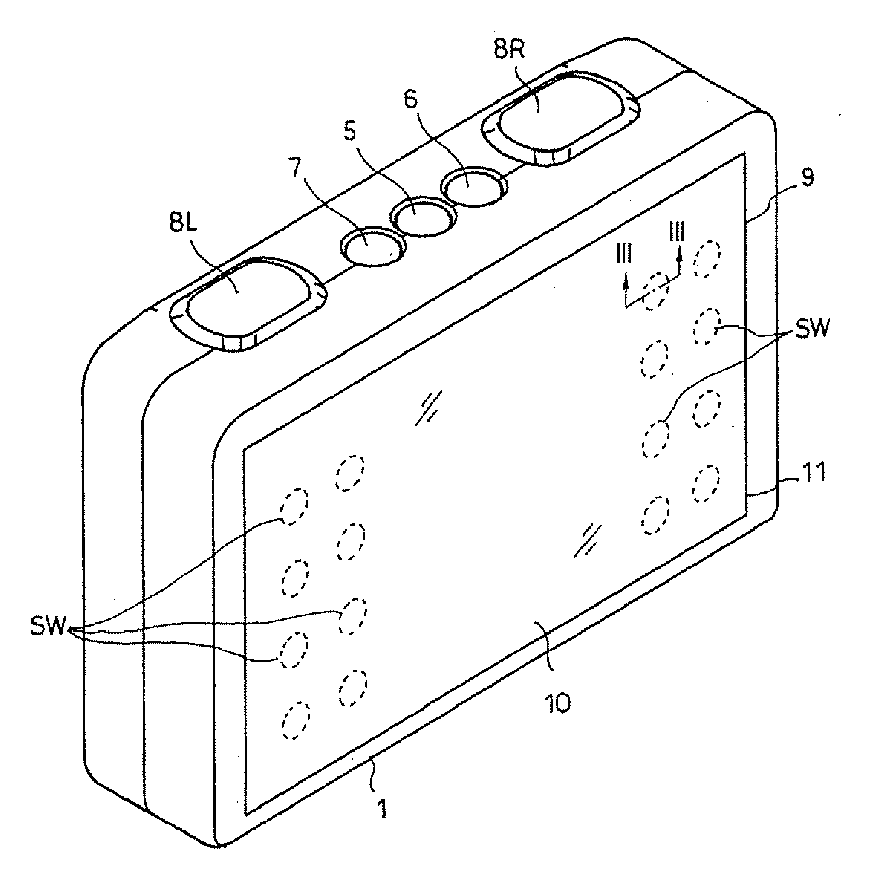
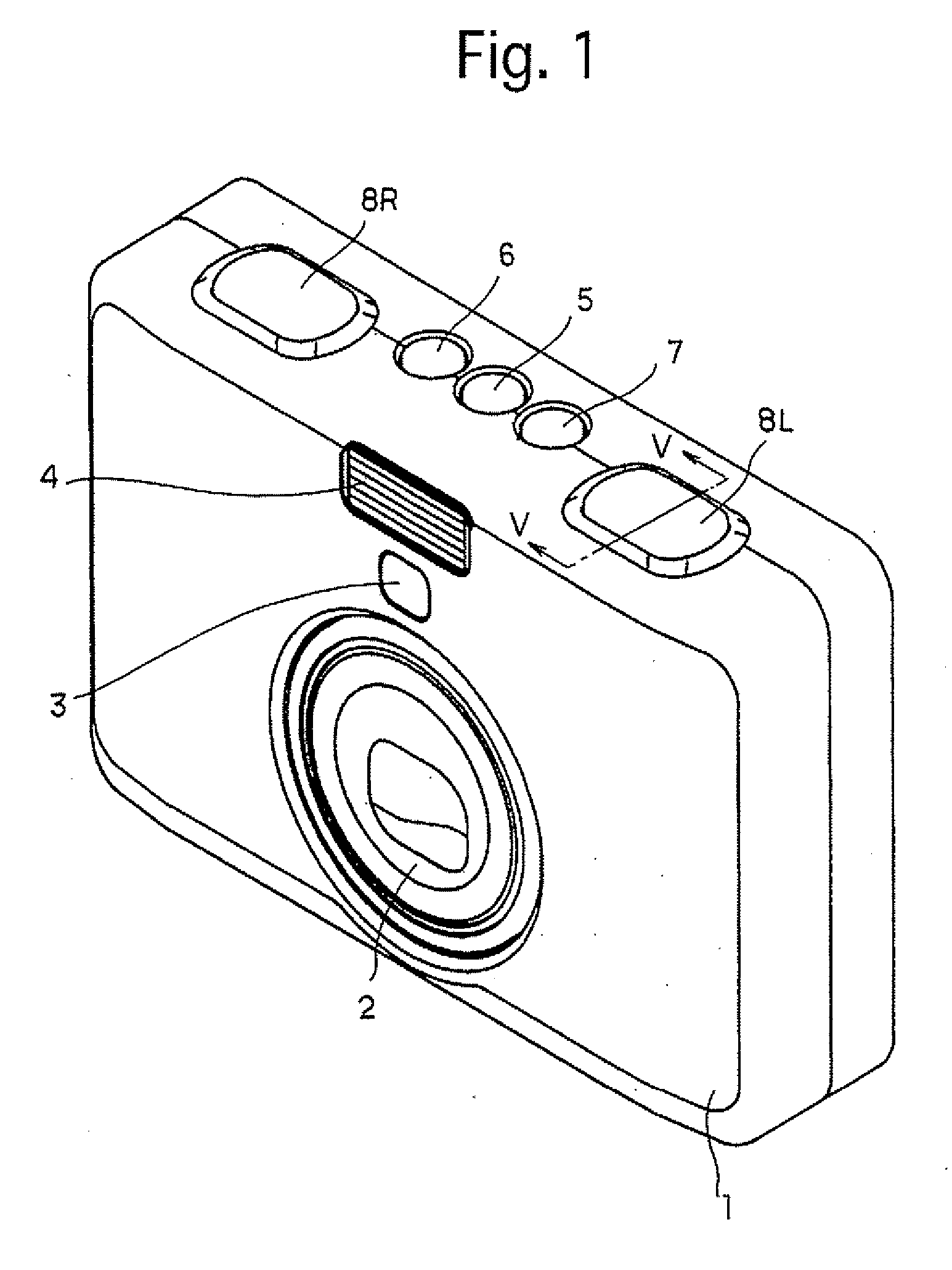
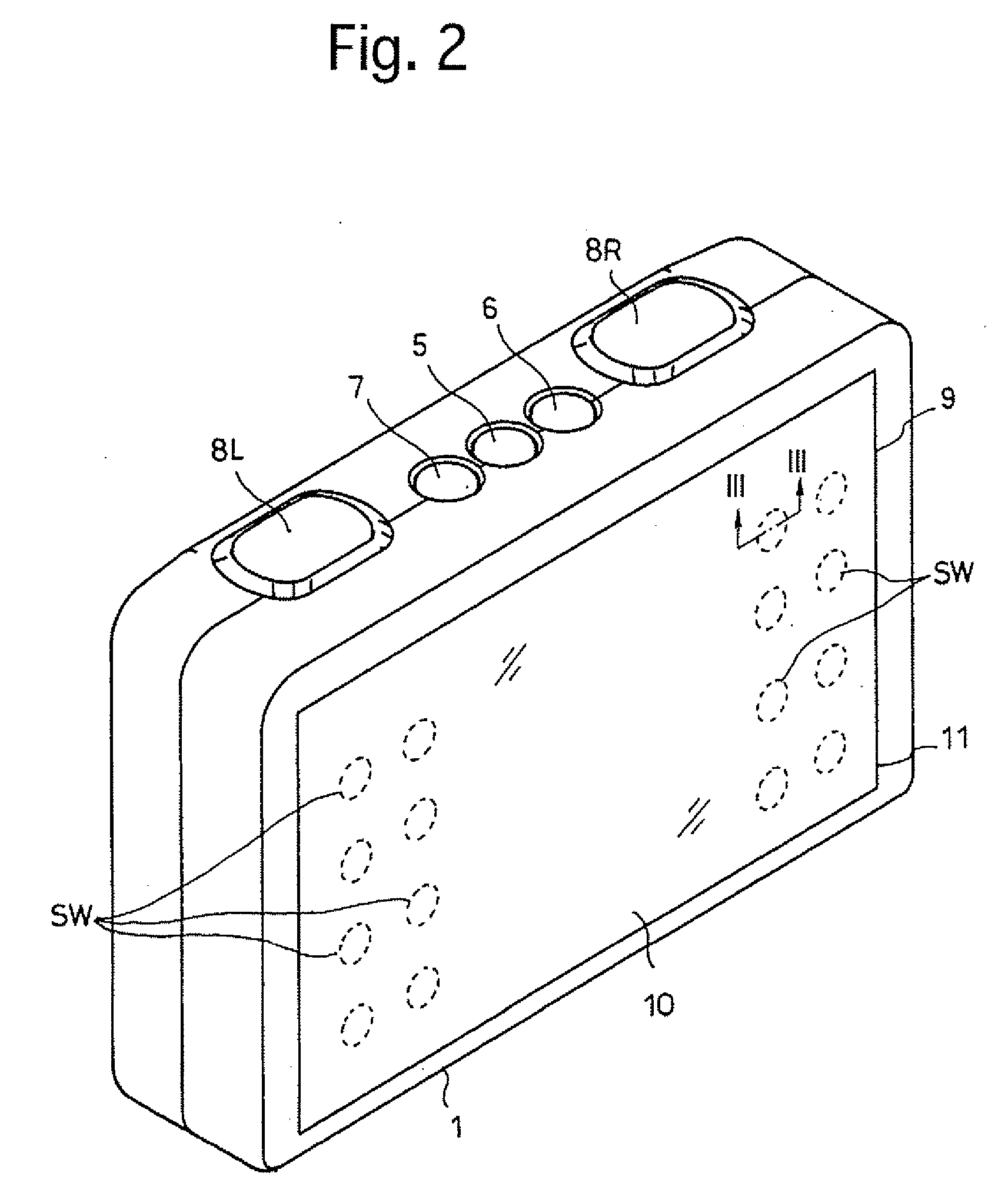
[0048]FIGS. 1 and 2 are front and rear perspective external views of the first embodiment of a digital camera having an electroluminescent display device according to the present invention, respectively. The digital camera is provided, on the front of a camera body 1 at a substantially center thereof, with a retractable photographing lens (photographing lens barrel) 2. The digital camera is provided, on the front of the camera body 1 above the photographing lens 2, with a self-portrait mirror 3 and a flash 4. The self-portrait mirror 3 is used when the photographer takes a self-portrait picture while visually checking his / her image viewed in the self-portrait mirror 3. The digital camera is provided on the top surface of the camera body 1 with a main switch (main switch button / power switch) 5, a replay button 6 and an EL (electroluminescent) display ON / OFF button 7. The digital camera is provided, on the top surface of the camera body 1 on laterally opposite sides ...

second embodiment

[Second Embodiment]

[0067]FIG. 11 is a front perspective view of the second embodiment of the digital camera, wherein portions and elements similar to those in the first embodiment of the digital camera shown in FIG. 1 are designated by the same reference numerals. In the second embodiment of the digital camera, each of the right and left release buttons 8R and 8L is composed of an EL display and a switch positioned immediately below the EL display, and which of the right and left release buttons is currently enabled is visually indicated by the associated EL display. FIG. 12 is an enlarged cross sectional view taken along an XI-XI line shown in FIG. 11. In FIG. 12, the release button 8L (8R) is provided with an EL display 100 (instead of the push button member 82 of the first embodiment) and is further provided immediately below the EL display 100 with a switching board 81 which is the same as the switching board 81 provided in the first embodiment of the digital camera. The EL disp...


PUM


Abstract

An electroluminescent display device includes an electroluminescent display, and at least one switch which is positioned adjacent to an inner surface of the electroluminescent display, the switch being activated upon an outer surface of the electroluminescent display being pressed to resiliently deform the switch.

Description

BACKGROUND OF THE INVENTION [0001] 1. Field of the Invention [0002] The present invention relates to an electroluminescent display device and a camera which incorporates an electroluminescent display device used as a monitoring device, and more specifically relates to a digital camera which incorporates an enlarged monitoring device for displaying object images. [0003] 2. Description of the Prior Art [0004] LCDs (liquid crystal displays) are used as monitoring devices (LCD monitors) in digital cameras which are available on the market at the present time. Since the monitoring device is usually provided on the back of the camera though various operating switches that the user manually operates while looking through the monitoring device are also provided on the back of the camera, there is no other choice but to positioned the monitoring device on an area on the back of the camera which does not interfere with such various operating switches. Accordingly, there is a limit to how much...

Claims


Application Information

Patent Timeline
Patent Type & Authority Applications(United States)
IPC IPC(8): G03B17/18
CPCG03B13/02H04N5/23293H04N5/2251G03B17/20H04N23/50H04N23/633H04N23/631
Inventor KUROSAWA, YUICHI
Owner RICOH IMAGING COMPANY
Why Eureka
Try Eureka