Samples delivering device, method of manufacturing samples applicator, method of delivering samples, and base activation device

a technology of sample delivering device and sample, which is applied in the direction of chemical methods analysis, laboratory glassware, instruments, etc., can solve the problems of protein inability to be completely removed, slow process that reduces the throughput of generating arrays, and severe limitations, so as to prevent tangling, reliably activate, and simple mechanism

Inactive Publication Date: 2007-09-25
PSS BIO INSTR
View PDF26 Cites 7 Cited by
  • Summary
  • Abstract
  • Description
  • Claims
  • Application Information

AI Technical Summary

Benefits of technology

[0018]Due to the hook-like shape of the retention tip, the contact of the base with the fluids or spotting of the base by the fluids can be performed by upwardly or transversely moving the retention tips relative to the base. Further, relative movement of the base in contact with the fluids, particularly running along the base can be freely performed.
[0068]With the eighteenth aspect of the invention, the tube is formed so as to be a sort of container accommodating the solution for activation. Therefore, the base can come in contact with the solution while passing through the tube. Consequently, by using the device, the base can be activated, and can be immersed in the solution for a long time. Further, by using the feeder, the base can be tensioned and run in a manner to prevent tangling. Consequently, the base can be reliably activated by a simple mechanism.

Problems solved by technology

While such methods allow generation of arrays, they are hampered by a severe limitation.
The washing step needed when sets of reagents are changed is a slow process that reduces throughput when generating arrays.
In addition, if the washing step is not complete, there is possibility of cross-contamination, on the occasion of reusing the same tips.
Further, when the various proteins are treated as reagents, even if a washing step is included, there is a problem that proteins cannot be completely removed and re-using cannot be executed.
Furthermore, there is another problem in that the pins and jet components cannot be autoclaved during the manufacture of the arrays.

Method used


Image

  • Samples delivering device, method of manufacturing samples applicator, method of delivering samples, and base activation device
  • Samples delivering device, method of manufacturing samples applicator, method of delivering samples, and base activation device
  • Samples delivering device, method of manufacturing samples applicator, method of delivering samples, and base activation device

Examples


first embodiment

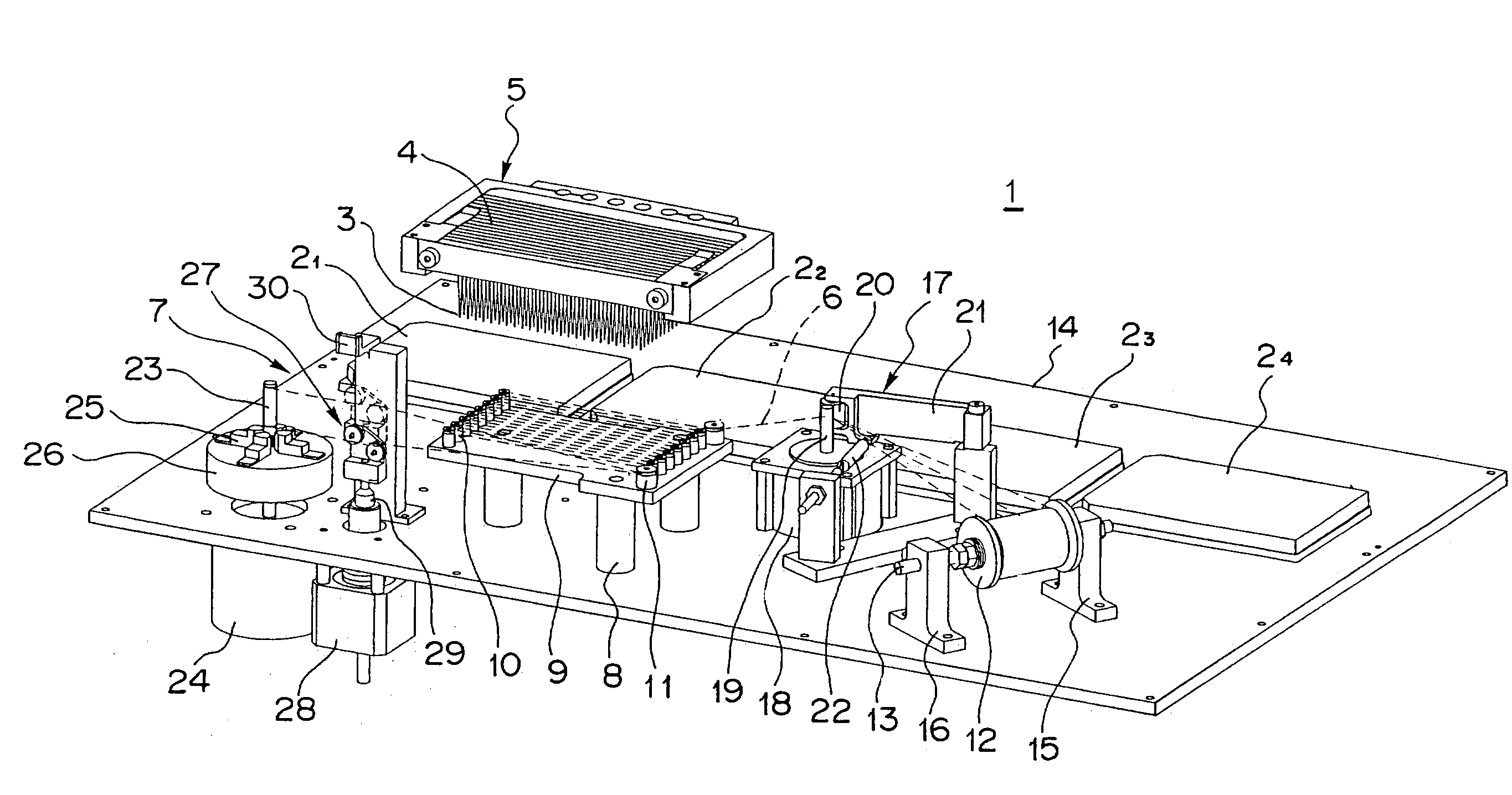
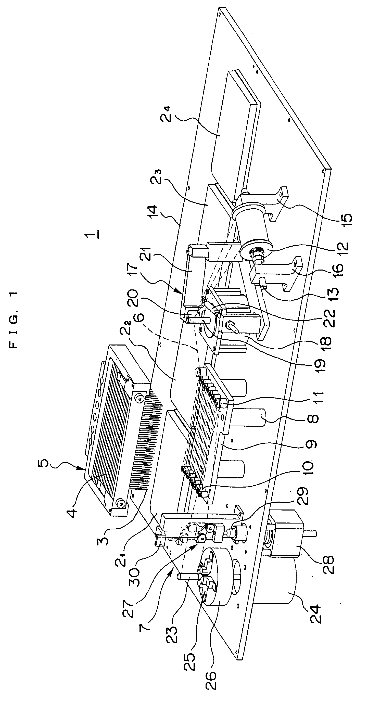
[0079]FIG. 1 shows an approximate overview of a samples delivering device 1 of a

[0080]The samples delivering device 1 is used so that multiple samples can be simultaneously treated. The samples delivering device 1 comprises a plurality of (four in this example) microplates 21, 22, 23, 24 having a plurality of wells accommodating various liquids including a plurality of extracted DNA of samples which are arranged so as to be matrix-like (24×16), and a samples supply section 5 having a matrix-like applicator 4 with two or more hooks 3 corresponding to the retention tips capable of retaining a small quantity of fluid by being dipped in each of the fluids accommodated in the wells of the microplates 21, 22, 23, 24, are arranged according to the arrangement of the wells.

[0081]Furthermore, the samples delivering device 1 comprises a base feeder 7 for arranging and tensioning a string-like base 6 to which predetermined samples are delivered, along a path determined according to the arrange...

second embodiment

[0117]FIG. 6 shows a samples delivering device 60 of a This samples delivering device 60 comprises a base feeder 61 and a sample supply section 63 having two matrix-like applicators 62 by which the applying components 30 are arranged in the shape of a matrix, 32 rows×48 columns (=1536 pieces), and application can be simultaneously performed at 3072 positions.

[0118]As shown in FIG. 6, the base feeder 61 comprises a supply reel 64, a take-up reel 65, thirty-two rollers 66 mounted at fixed intervals in accordance with the path of the base 6 between these reels, and a motor which carries out rotation drive of the supply reel 64 and the take-up reel 65, which is not shown in the drawings.

[0119]With this base feeder 61, by using the thirty-two rollers 66, the string-like base 6 is configured so that thirty-two columns may be formed substantially. The string-like base 6 is routed so as to be able to run from the supply reel 64 to the take-up reel 65. The matrix-like samples applicator 62 ...

third embodiment

[0122]FIG. 7(a) shows a samples delivering device of a The samples delivering device has a matrix-like applicator 71 of 2 rows×48 columns, which has a comb-like support section 70 which supports two rows of the applying components 69 comprising the arm section 67 and the retention tip 68. Sixteen matrix-like applicators 71 arranged in parallel, correspond to the matrix-like applicator of 32 rows×48 columns.

[0123]As shown in FIGS. 7(b) and 7(c), the matrix-like applicators 71 are arranged so that the interval between the adjoining matrix-like applicators 71 can insert the comb-like support section 70 in the gap between adjoining rollers 73 with which the base feeder 72 configures the string-like base 6 and adjoining string-like bases 6. Moreover, the interval between the retention tips 68 of the one applying component 69 is the interval between the rows that the corresponding string-like base 6 adjoins, and consequently the distance between the adjacent wells 74 of a microplate.

[012...


PUM

PropertyMeasurementUnit
volumeaaaaaaaaaa
volumeaaaaaaaaaa
thickaaaaaaaaaa

Abstract

The present invention relates to a samples delivering device, a method of manufacturing a samples applicator, a method of delivering samples, and a base activation device which can handle a plurality of various samples, efficiently and promptly. The invention is constructed so as to have: one or more sets of vessels capable of accommodating fluids containing predetermined samples to be delivered to a base or one or more sets of vessels, a samples supply section having a samples applicator, wherein two or more retention tips capable of retaining a small quantity of fluids by being dipped in each of the fluids accommodated in the vessels are arranged according to the vessels, and a transfer means for relatively moving between the base and the one or more sets of vessels, and the applicator.

Description

CROSS REFERENCE TO RELATED APPLICATION[0001]This application claims priority to U.S. provisional patent application No. 60 / 383,731, filed on May 28, 2002.FIELD OF THE INVENTION[0002]The present invention relates to a samples delivering device, a method of manufacturing a samples applicator, a method of delivering samples, and a base activation device. Particularly, the present invention relates to a samples delivering device, a method of manufacturing a samples applicator, a method of delivering samples, and a base activation device which enable extraction and transfer of many various samples. The present invention relates to all manner of fields, for example, in which arrays arranged with materials such as nucleic acids, proteins or sugars are prepared, a large number of various samples are mixed for combinatorial chemistry, or standard immunoassay is executed, by using a multi-well plate format.BACKGROUND OF THE INVENTION[0003]Currently, the phenomenal increase in the use of high ...

Claims


Application Information

Patent Timeline
Patent Type & Authority Patents(United States)
IPC IPC(8): B01L3/02G01N35/00B01L3/00G01N35/10
CPCB01L3/0244B01L3/0255B01L3/50853B01L9/547G01N35/1074B01L3/563B01L2200/12Y10T436/2575B01L2300/0829G01N2035/1037Y10T436/15Y10T436/110833B01L2300/046
Inventor STIMPSON, DONALD I.TAJIMA, HIDEJI
Owner PSS BIO INSTR
Why Eureka
Try Eureka