Cooling system, vehicle equipped with the cooling system, and method for controlling the cooling system

a technology of cooling system and cooling system, which is applied in the direction of motor/generator/converter stopper, process and machine control, engine-driven generators, etc., can solve the problem of excessive operating noise and achieve the effect of reliably activating the blower and avoiding excessive operating noise when the blower is activated

Active Publication Date: 2013-04-16
TOYOTA JIDOSHA KK
View PDF13 Cites 6 Cited by
  • Summary
  • Abstract
  • Description
  • Claims
  • Application Information

AI Technical Summary

Benefits of technology

[0007]A cooling system, a vehicle equipped with the cooling system, and a method for controlling a cooling system of the present invention more reliably activates a blower, such as an electric fan, and avoids generating excessive operating noise when the blower is activated.
[0009]According to the cooling system, the effective voltage of the electric power to drive the electric fan is sufficient to prevent the output torque when the electric fan is activated from being too low, even if the voltage of the power source is relatively low, when the activating condition for the electric fan is satisfied, and the effective voltage of the electric power to drive the electric fan is low enough to prevent the output torque when the electric fan is activated from increasing too high, even if the voltage of the power source is relatively high, when the activating condition for the electric fan is satisfied. Therefore, the cooling system of the present invention can more reliably activate the electric fan and avoid generating excessive operating noise of the electric fan, due to an excessive increase of the rotational speed of the electric fan, immediately after the activation of the electric fan.
[0010]The cooling system of the present invention may further include: a temperature obtaining device that obtains the temperature of the target object; and a setting device that sets a target rotational speed for the electric fan based on the obtained temperature. The activation condition may be satisfied when the obtained temperature is at least equal to a prescribed temperature. The cancellation condition may be satisfied when the rotational speed of the electric fan reaches a prescribed rotational speed that is lower than the target rotational speed. Also, in this cooling system, the control device may set a duty ratio that becomes the rotational speed of the electric fan equal to the set target rotational speed after the cancellation condition has been satisfied and may control the switching device based on the set duty ratio. In this way, it is possible to avoid generation excessive operating noise due to an excessive increase in the rotational speed of the electric fan immediately after the activation of the electric fan, and the rotational speed of the electric fan may be reached at a target rotational speed quickly after the rotational speed has increased to a certain extent.
[0011]A vehicle may be equipped with any one of the cooling systems described above, and may have an electric motor that outputs power for running; and an electric storage device, as the target object, that is capable of supplying electric power to and accepting electric power from the electric motor. Because the vehicle of the present invention is equipped with a cooling system according to any one of the aspects of the present invention described above, provides the same effects as those of the cooling system of the present invention, including the effect that the generation of excessive operating noise immediately after the activation of the electric fan may be avoided, and thereby does not annoy the passengers.
[0012]A second aspect of the present invention relates to a method for controlling a cooling system. The control method includes: controlling a switching device that is connected to a power source and an electric fan, which is driven by electric power from the power source and capable of blowing air to cool a specific target object, so that air is supplied from the electric fan when a target object is cooled, and controlling the switching device from the moment when an activation condition for the electric fan is satisfied until the moment when a predetermined cancellation condition is satisfied so that the higher the detected voltage is when the activation condition is satisfied, the lower the duty ratio is set.
[0013]According to the method for controlling a cooling system, the effective voltage of the electric power driving the electric fan is high enough to prevent the output torque when the electric fan is activated from being insufficient even if the voltage of the power source is relatively low when the activating condition for the electric fan is satisfied. In addition, the effective voltage of the electric power is low enough to prevent the output torque when the electric fan is activated from increasing excessively even if the voltage of the power source is relatively high when the activating condition for the electric fan is satisfied. Therefore, the method for controlling a cooling system of the present invention more reliably activates the electric fan and avoid generating excessive operating noise of the electric fan due to an excessive increase of the rotational speed of the electric fan at the time of the activation of the electric fan.

Problems solved by technology

However, if the duty ratio used to activate the fan is set high to allow reliable activation of the fan, the rotational speed of the fan may be excessive, resulting in excessive operating noise.

Method used


Image

  • Cooling system, vehicle equipped with the cooling system, and method for controlling the cooling system
  • Cooling system, vehicle equipped with the cooling system, and method for controlling the cooling system
  • Cooling system, vehicle equipped with the cooling system, and method for controlling the cooling system

Examples


Embodiment Construction

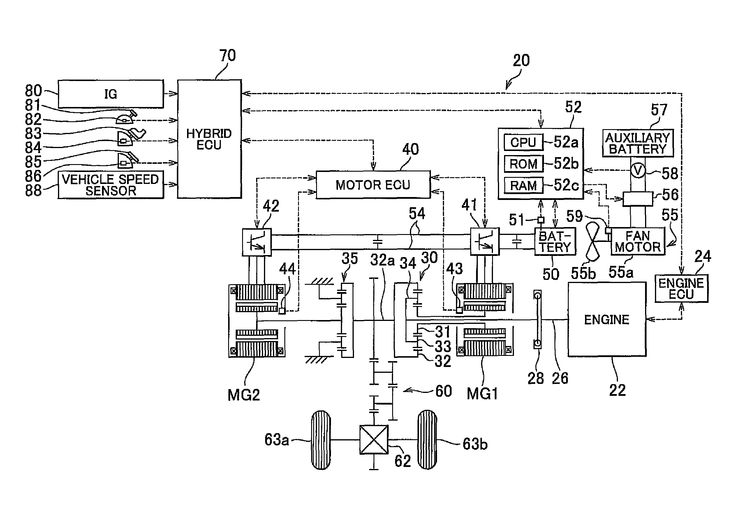
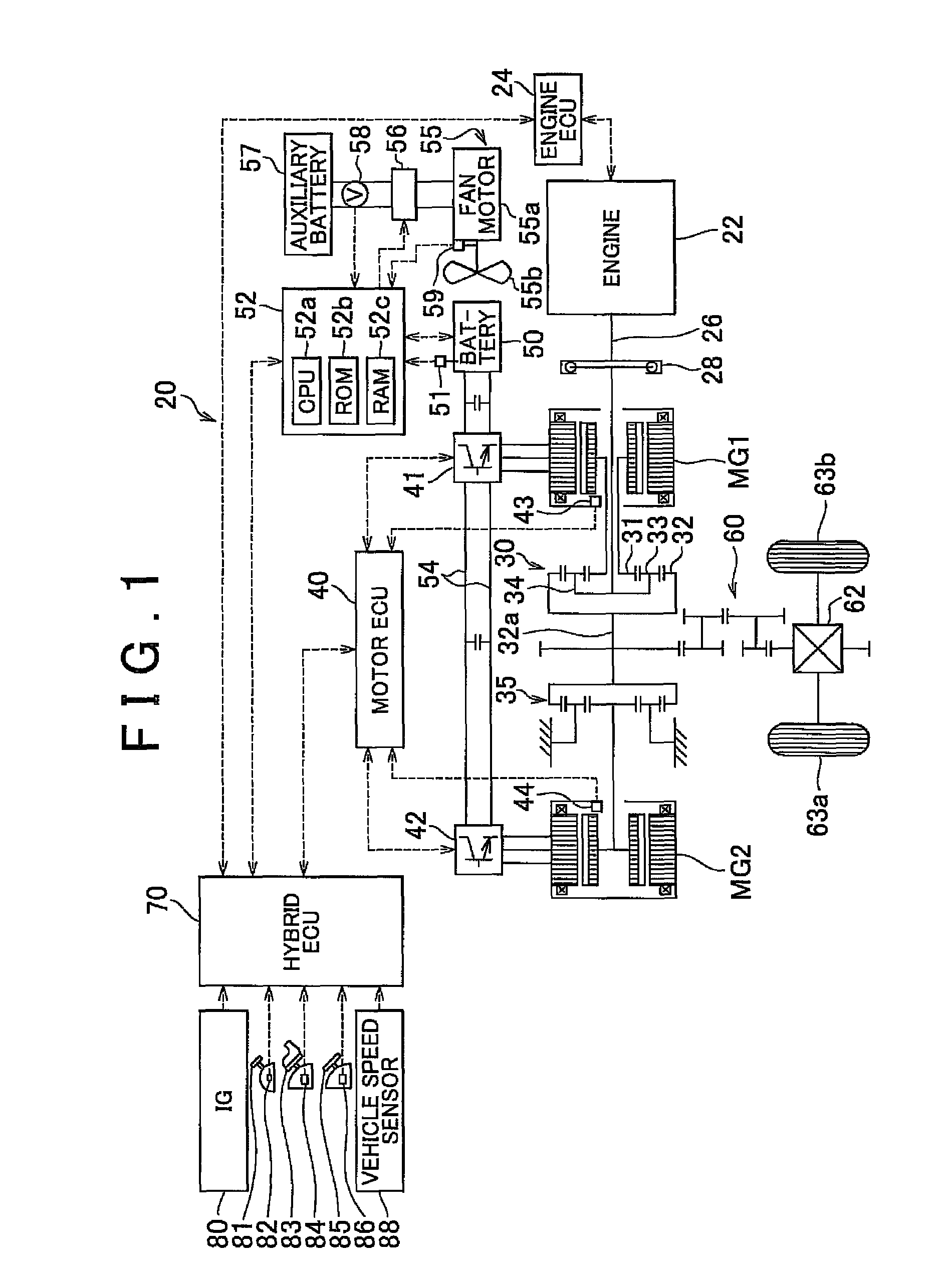
[0024]FIG. 1 is a configuration diagram that illustrates an overview of the configuration of a hybrid vehicle 20 equipped with a cooling system according to an embodiment of the present invention. The hybrid vehicle 20 of this embodiment includes an engine 22; a three-shaft type power distribution-integration mechanism 30 that is connected to a crankshaft 26 (output shaft) of the engine 22 via a damper 28; a motor MG1 that is connected to the power distribution-integration mechanism 30 and is able to generate electric power; a reduction gear 35 that is attached to a ring gear shaft 32a connected to the power distribution-integration mechanism 30; a motor MG2 that is connected to the reduction gear 35; a battery 50 that is exchanges electric power with the motors MG1 and MG2; an electric cooling fan 55 that cools the battery 50; a battery electronic control unit (which is hereinafter referred to as “battery ECU 52”) that manages the battery 50 and controls the cooling fan 55; and a h...


PUM

PropertyMeasurementUnit
rated output voltageaaaaaaaaaa
voltageaaaaaaaaaa
output voltageaaaaaaaaaa

Abstract

A fan motor is controlled via a switching circuit from the moment when a cooling fan control routine is started until the moment when the rotational speed of the fan motor reaches a control-switching speed so that the higher the detected auxiliary battery voltage is when the cooling fan control is started, the lower the command duty ratio that is set. Accordingly, it is possible to activate the fan motor more reliably and to avoid generating excessive operating noise by the cooling fan when the fan motor is activated.

Description

INCORPORATION BY REFERENCE[0001]The disclosure of Japanese Patent Application No. 2008-324549 filed on Dec. 19, 2008, including the specification, drawings and abstract is incorporated herein by reference in its entirety.BACKGROUND OF THE INVENTION[0002]1. Field of Invention[0003]The present invention relates to a cooling system, a vehicle equipped with the cooling system, and a method for controlling the cooling system.[0004]2. Description of Related Art[0005]A system that is mounted on a vehicle and that uses a fan for cooling a battery has been described in which, if the temperature of the battery is equal to or below a specified maximum threshold temperature, the fan is driven while the control duty ratio that is required based on the temperature and the heat generation amount of the battery is limited to maintain an acceptable noise level of the operating noise of the fan in accordance with the vehicle speed (for example, see Japanese Patent Application Publication No. 2003-178...

Claims


Application Information

Patent Timeline
Patent Type & Authority Patents(United States)
IPC IPC(8): B60W10/26B60K6/445B60K6/52B60K11/06B60L50/16B60W10/30B60W20/00H01M10/60H01M10/613H01M10/625H01M10/633H01M10/6563H02P6/08
CPCB60L11/187B60L11/1872H01M10/48H01M10/486H01M10/5016H01M10/5022H01M10/5067H01M10/5004B60W2510/246Y02T10/705Y02T10/7005H01M10/625H01M10/633H01M10/6563H01M10/613B60L58/24B60L58/25Y02T10/70Y02E60/10B60W2510/244
Inventor NAKAMURA, KIMIHITOKIKUCHI, YOSHIAKISUZUKI, MASAHITO
Owner TOYOTA JIDOSHA KK
Why Eureka
Try Eureka