[0007]A cooling system, a vehicle equipped with the cooling system, and a method for controlling a cooling system of the present invention more reliably activates a blower, such as an electric fan, and avoids generating excessive operating noise when the blower is activated.
[0009]According to the cooling system, the effective
voltage of the
electric power to drive the electric fan is sufficient to prevent the output torque when the electric fan is activated from being too low, even if the
voltage of the power source is relatively low, when the activating condition for the electric fan is satisfied, and the effective
voltage of the
electric power to drive the electric fan is low enough to prevent the output torque when the electric fan is activated from increasing too high, even if the voltage of the power source is relatively high, when the activating condition for the electric fan is satisfied. Therefore, the cooling system of the present invention can more reliably activate the electric fan and avoid generating excessive operating noise of the electric fan, due to an excessive increase of the rotational speed of the electric fan, immediately after the activation of the electric fan.
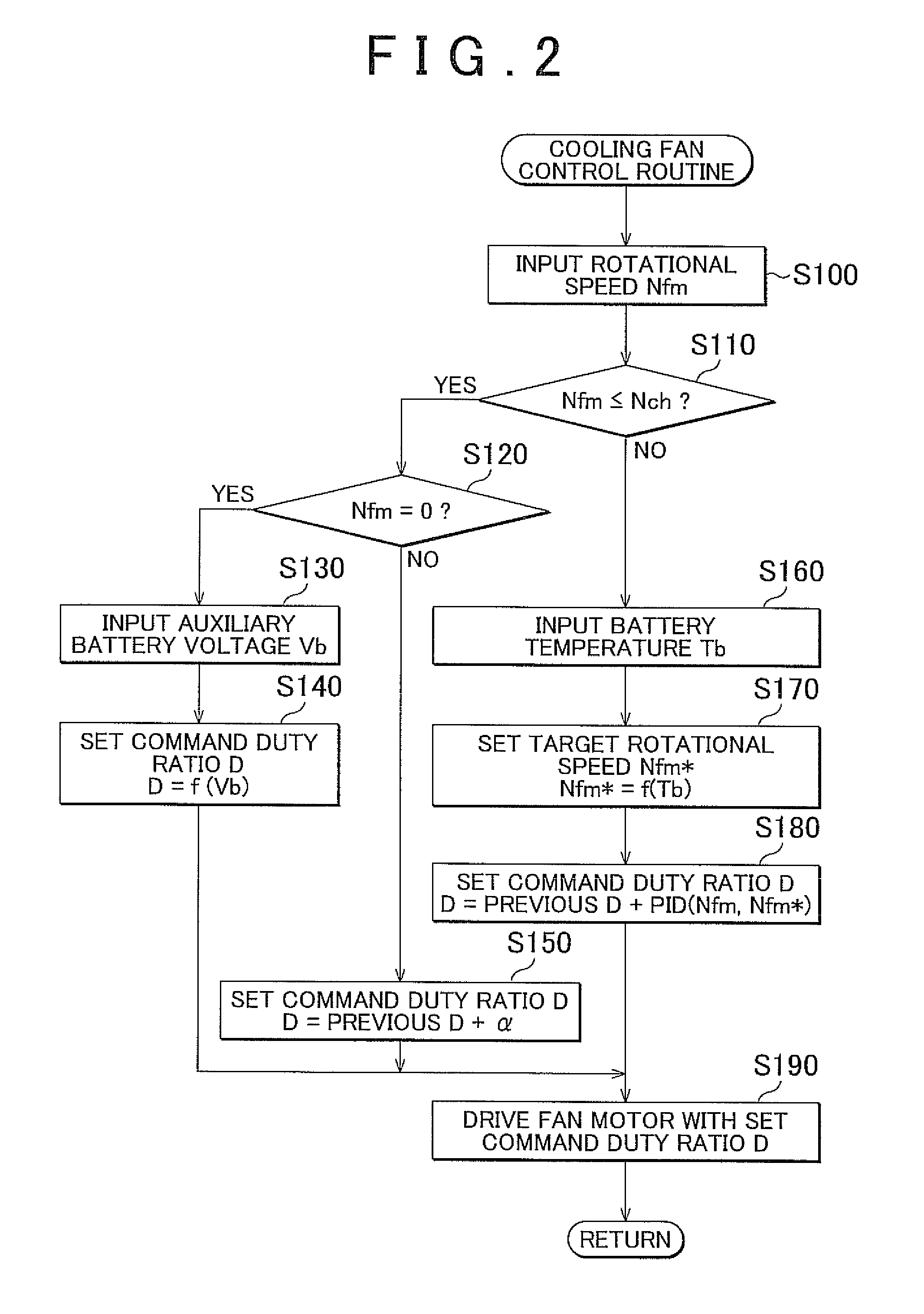
[0010]The cooling system of the present invention may further include: a temperature obtaining device that obtains the temperature of the target object; and a setting device that sets a target rotational speed for the electric fan based on the obtained temperature. The activation condition may be satisfied when the obtained temperature is at least equal to a prescribed temperature. The cancellation condition may be satisfied when the rotational speed of the electric fan reaches a prescribed rotational speed that is lower than the target rotational speed. Also, in this cooling system, the control device may set a duty ratio that becomes the rotational speed of the electric fan equal to the set target rotational speed after the cancellation condition has been satisfied and may control the switching device based on the set duty ratio. In this way, it is possible to avoid generation excessive operating noise due to an excessive increase in the rotational speed of the electric fan immediately after the activation of the electric fan, and the rotational speed of the electric fan may be reached at a target rotational speed quickly after the rotational speed has increased to a certain extent.
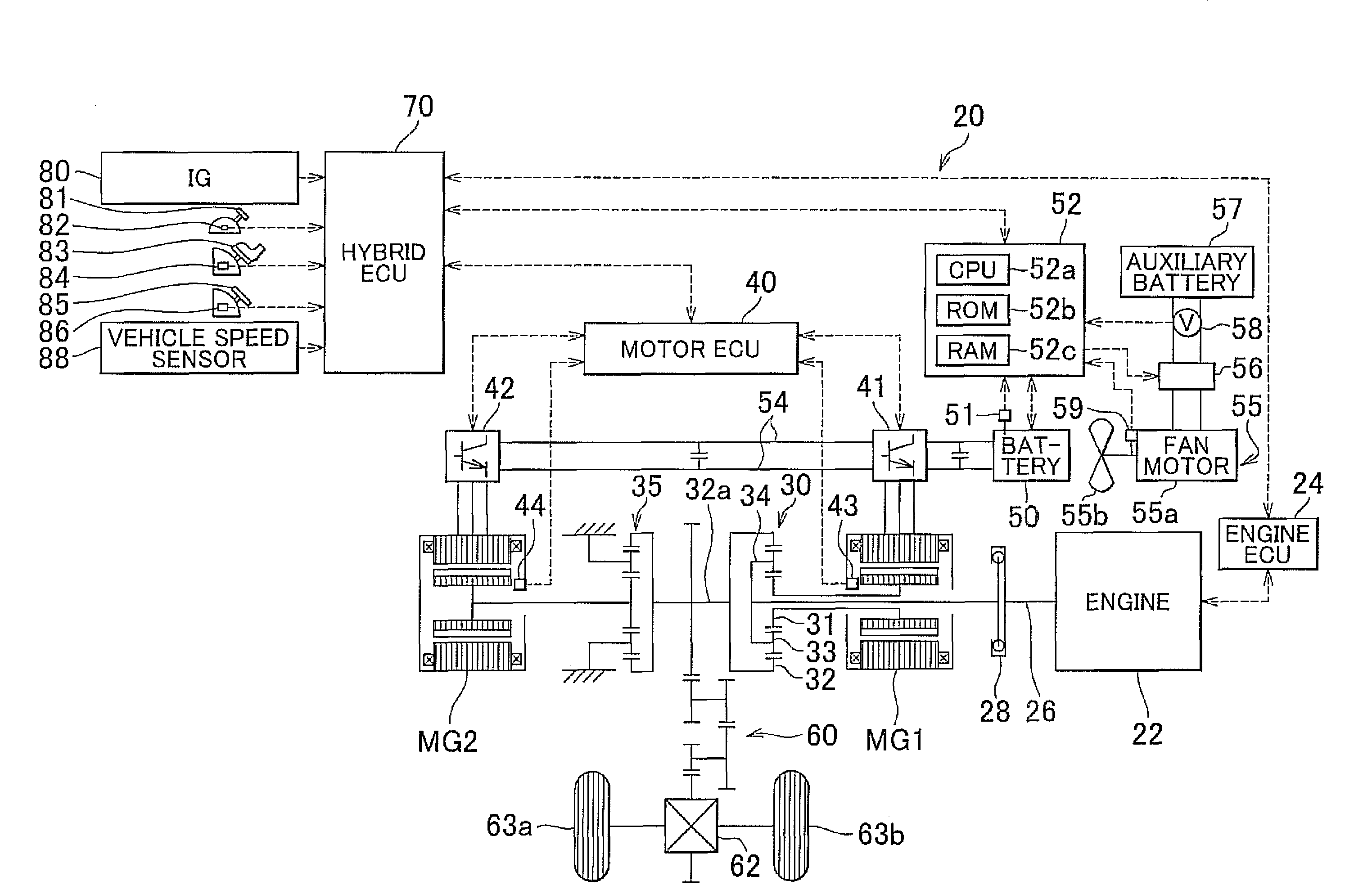
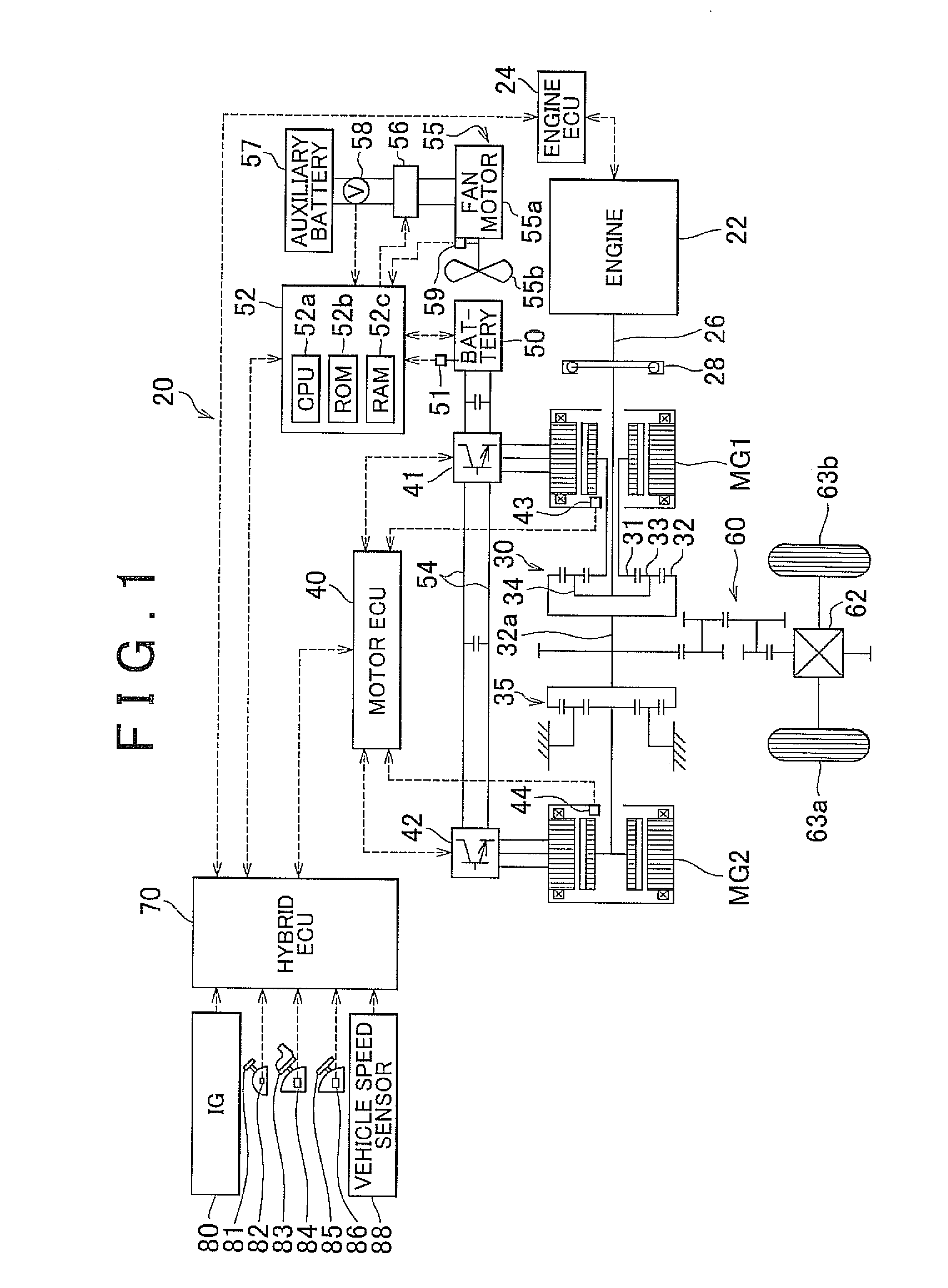
[0011]A vehicle may be equipped with any one of the cooling systems described above, and may have an
electric motor that outputs power for running; and an electric storage device, as the target object, that is capable of supplying
electric power to and accepting electric power from the
electric motor. Because the vehicle of the present invention is equipped with a cooling system according to any one of the aspects of the present invention described above, provides the same effects as those of the cooling system of the present invention, including the effect that the generation of excessive operating noise immediately after the activation of the electric fan may be avoided, and thereby does not annoy the passengers.
[0012]A second aspect of the present invention relates to a method for controlling a cooling system. The control method includes: controlling a switching device that is connected to a power source and an electric fan, which is driven by electric power from the power source and capable of blowing air to cool a specific target object, so that air is supplied from the electric fan when a target object is cooled, and controlling the switching device from the moment when an activation condition for the electric fan is satisfied until the moment when a predetermined cancellation condition is satisfied so that the higher the detected voltage is when the activation condition is satisfied, the lower the duty ratio is set.
[0013]According to the method for controlling a cooling system, the effective voltage of the electric power driving the electric fan is high enough to prevent the output torque when the electric fan is activated from being insufficient even if the voltage of the power source is relatively low when the activating condition for the electric fan is satisfied. In addition, the effective voltage of the electric power is low enough to prevent the output torque when the electric fan is activated from increasing excessively even if the voltage of the power source is relatively high when the activating condition for the electric fan is satisfied. Therefore, the method for controlling a cooling system of the present invention more reliably activates the electric fan and avoid generating excessive operating noise of the electric fan due to an excessive increase of the rotational speed of the electric fan at the time of the activation of the electric fan.

