Tool guide

a tool guide and tool technology, applied in the field of machining workpieces, can solve the problems of frequent inaccurate holes, low accuracy of drilling holes, and inability to accurately position the inserted tool, and achieve the effect of precise perpendicular positioning of the inserted tool

Inactive Publication Date: 2007-01-25
ORE JEREMY E
View PDF28 Cites 7 Cited by
  • Summary
  • Abstract
  • Description
  • Claims
  • Application Information

AI Technical Summary

Benefits of technology

[0011] Another advantage of interchangeable tool receivers is that the aperture positioning member itself is not worn with use, because tools are received by the tool receivers, not the aperture itself. In addition, the tool receiver provides substantial support to a tool shank, thus ensuring precise perpendicular positioning of the inserted tool. The tool receiver may also be constructed from a non-ferrous material, thereby eliminating the common problem of metal chips adhering to a tool guide.

Problems solved by technology

A major problem associated with hand drilling is that of producing a hole such that its longitudinal axis is perpendicular to the workpiece surface in which the hole is drilled.
However, such jigs and fixtures are of little use in solving the hand drilling problems faced by home craftsmen or even by professional machinists.
Inaccurate holes are frequently the result.
The problems associated with hand tapping holes are at least as great as those associated with hand drilling.
Even if the hole to be tapped is accurate, there is no assurance that the hole will be tapped in an acceptable manner.
It is especially problematic when the workpiece is large, immovable, marginally accessible, in an unusual or uncomfortable orientation, or otherwise not amenable to the use of traditional precision tools, such as a drill press.

Method used


Image

  • Tool guide
  • Tool guide
  • Tool guide

Examples


Embodiment Construction

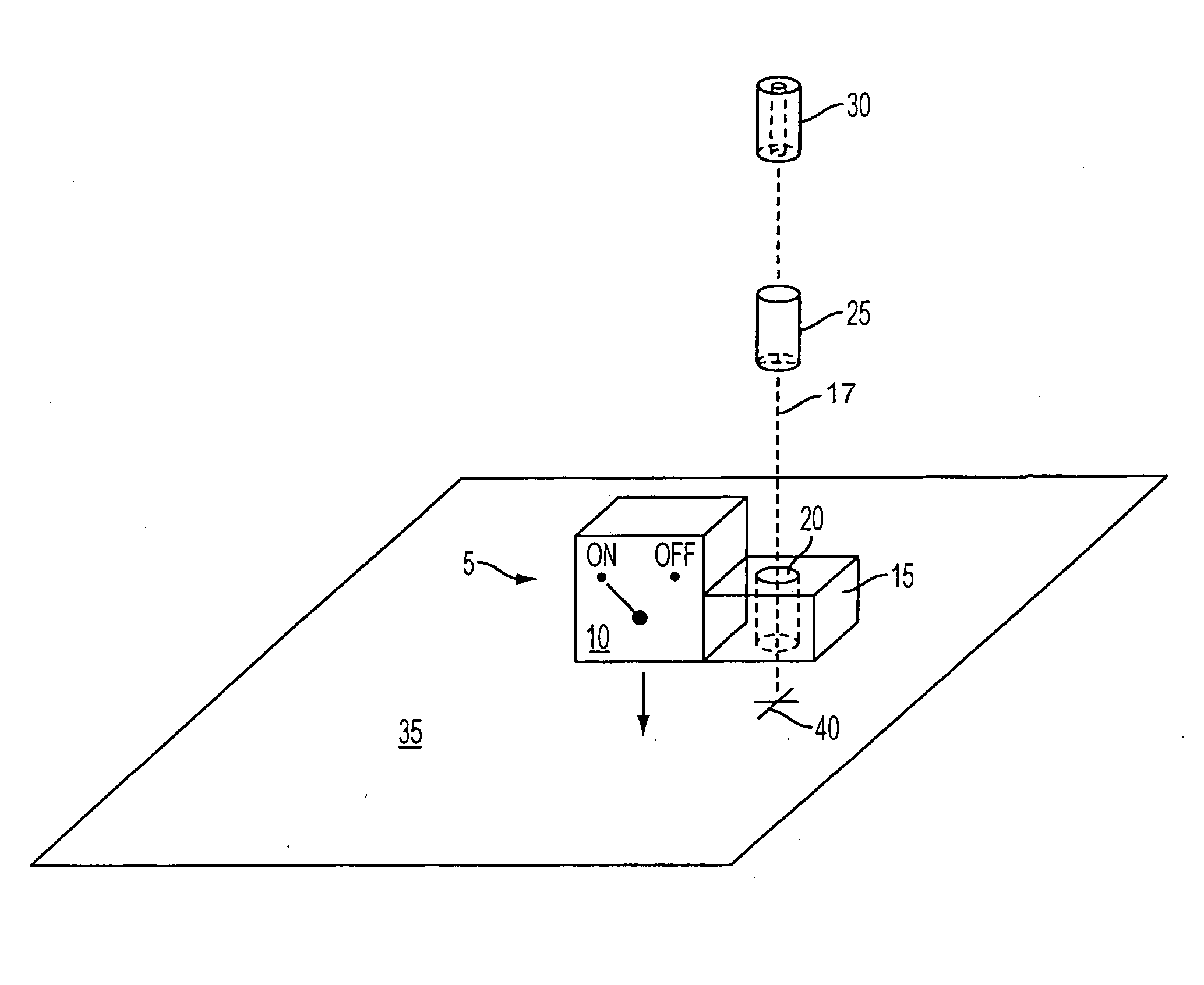
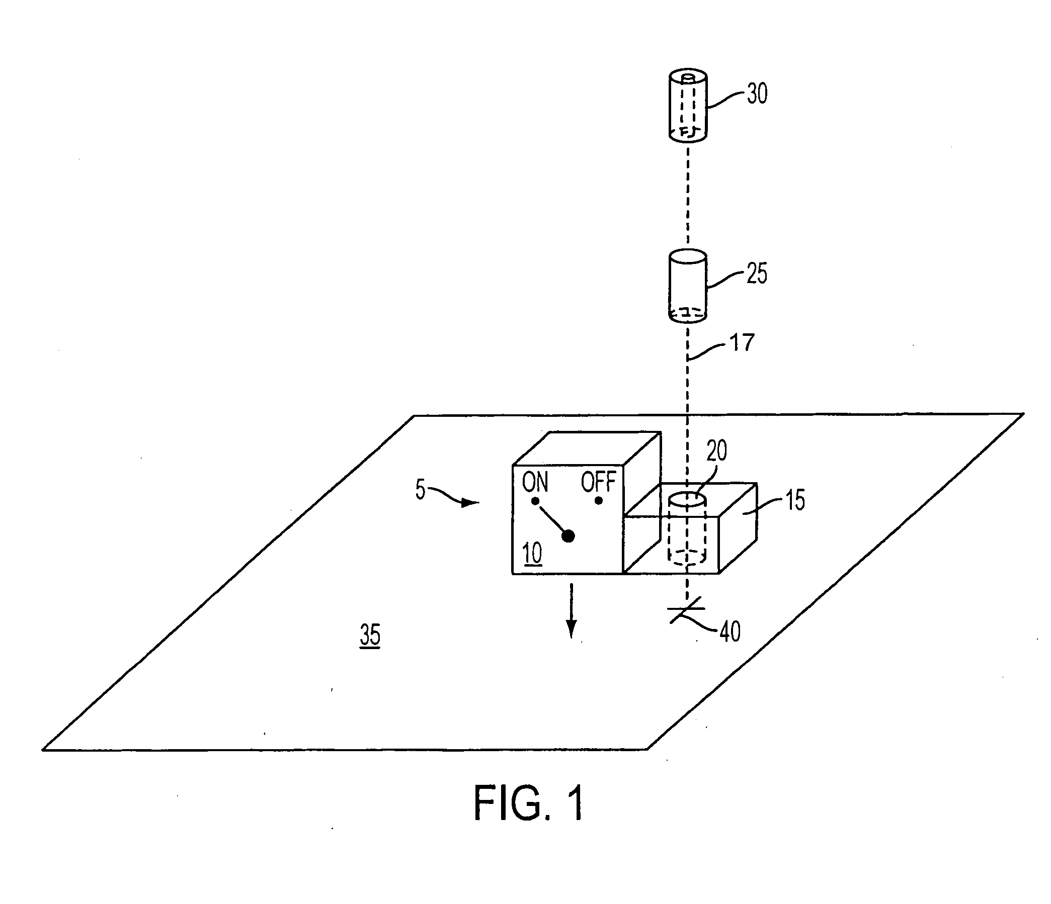
[0020] In the following paragraphs, the present invention will be described in detail by way of example with reference to the attached drawings. While this invention is capable of embodiment in many different forms, specific embodiments are shown in the drawings and will herein be described in detail with the understanding that the present disclosure is to be considered as an example of the principles of the invention and not intended to limit the invention to the specific embodiments shown and described. That is, throughout this description, the embodiments and examples shown should be considered as exemplars, rather than as limitations on the present invention. Descriptions of well known components, methods and / or processing techniques are omitted so as to not unnecessarily obscure the invention. As used herein, the “present invention” refers to any one of the embodiments of the invention described herein, and any equivalents. Furthermore, reference to various feature(s) of the “p...


PUM

PropertyMeasurementUnit
magnetic fieldaaaaaaaaaa
transparentaaaaaaaaaa
magnetically attractiveaaaaaaaaaa

Abstract

A tool guide apparatus and method is provided. One embodiment of the invention includes a positioning block having an aperture into which a transparent aperture center indicator is placed. An activateable coupling member is coupled to the positioning block and rigidly couples the tool guide to a workpiece. The aperture center indicator is replaced with a tool receiver that includes an aperture for receiving a tool. This Abstract is provided for the sole purpose of complying with the Abstract requirement rules that allow a reader to quickly ascertain the subject matter of the disclosure contained herein. This Abstract is submitted with the explicit understanding that it will not be used to interpret or to limit the scope or the meaning of the claims.

Description

FIELD OF THE INVENTION [0001] The present invention generally relates to machining workpieces. More particularly, the invention concerns an apparatus, system and method to guide tools. BACKGROUND OF THE INVENTION [0002] It is well known to drill and tap holes by hand. A great number of electric hand-held drills are in everyday use by both professional and amateur machinists and craftsmen. Similarly, hand-tapping threads into a workpiece is a common practice. [0003] A major problem associated with hand drilling is that of producing a hole such that its longitudinal axis is perpendicular to the workpiece surface in which the hole is drilled. Jigs and fixtures are commonly used to guide drills in production operations used in industry. However, such jigs and fixtures are of little use in solving the hand drilling problems faced by home craftsmen or even by professional machinists. With hand operations, the person frequently must rely only on his eye to properly align the drill both bef...

Claims


Application Information

Patent Timeline
Patent Type & Authority Applications(United States)
IPC IPC(8): B23B47/28
CPCB23B49/026Y10T408/554B23B2270/34B23B2260/10
Inventor ORE, JEREMY E.
Owner ORE JEREMY E
Why Eureka
Try Eureka