
Method for the production of a fibre composite material component and intermediate product for such a method

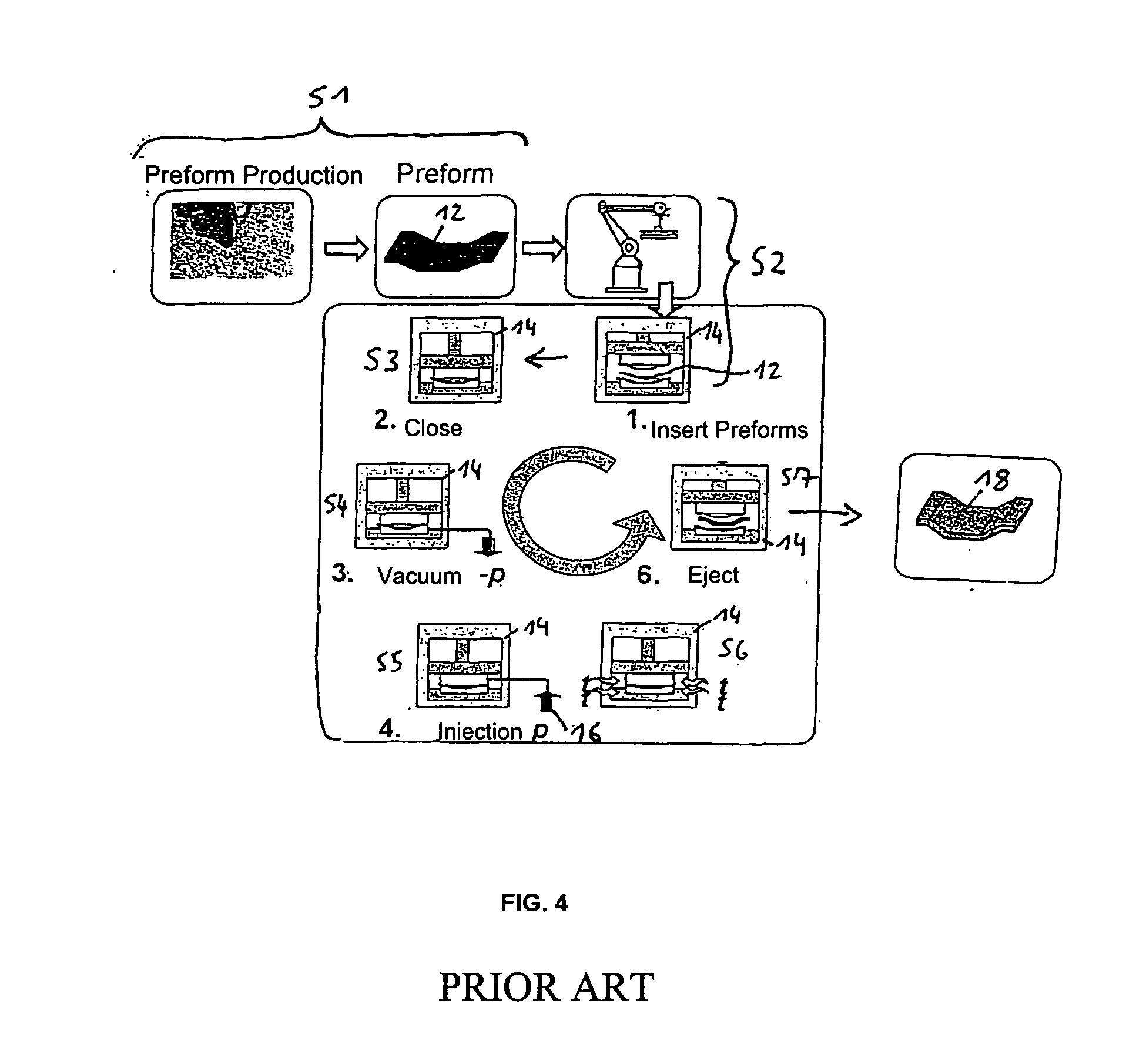
a composite material and intermediate product technology, applied in the direction of sustainable transportation, transportation and packaging, chemistry apparatus and processes, etc., can solve the problems of unfavorable fiber pattern or even destruction of fibers, disturbing and reducing the strength of fiber composite materials. , the effect of natural relaxation

Inactive Publication Date: 2007-01-25
AIRBUS HELICOPTERS DEUT GMBH
View PDF4 Cites 16 Cited by
  • Summary
  • Abstract
  • Description
  • Claims
  • Application Information

AI Technical Summary

Benefits of technology

[0016] The method according to the invention makes it possible to largely avoid the drawbacks associated with the state of the art in a simple, effective and advantageous manner as well as to achieve a high-quality component made of fiber composite material having improved mechanical properties.
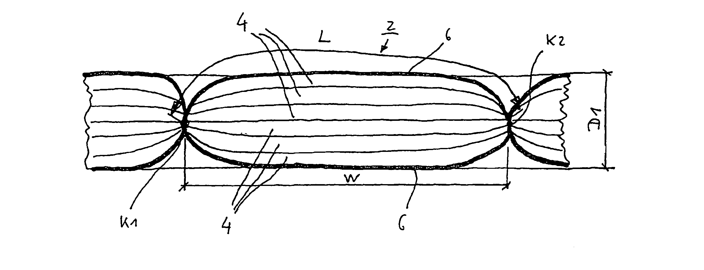
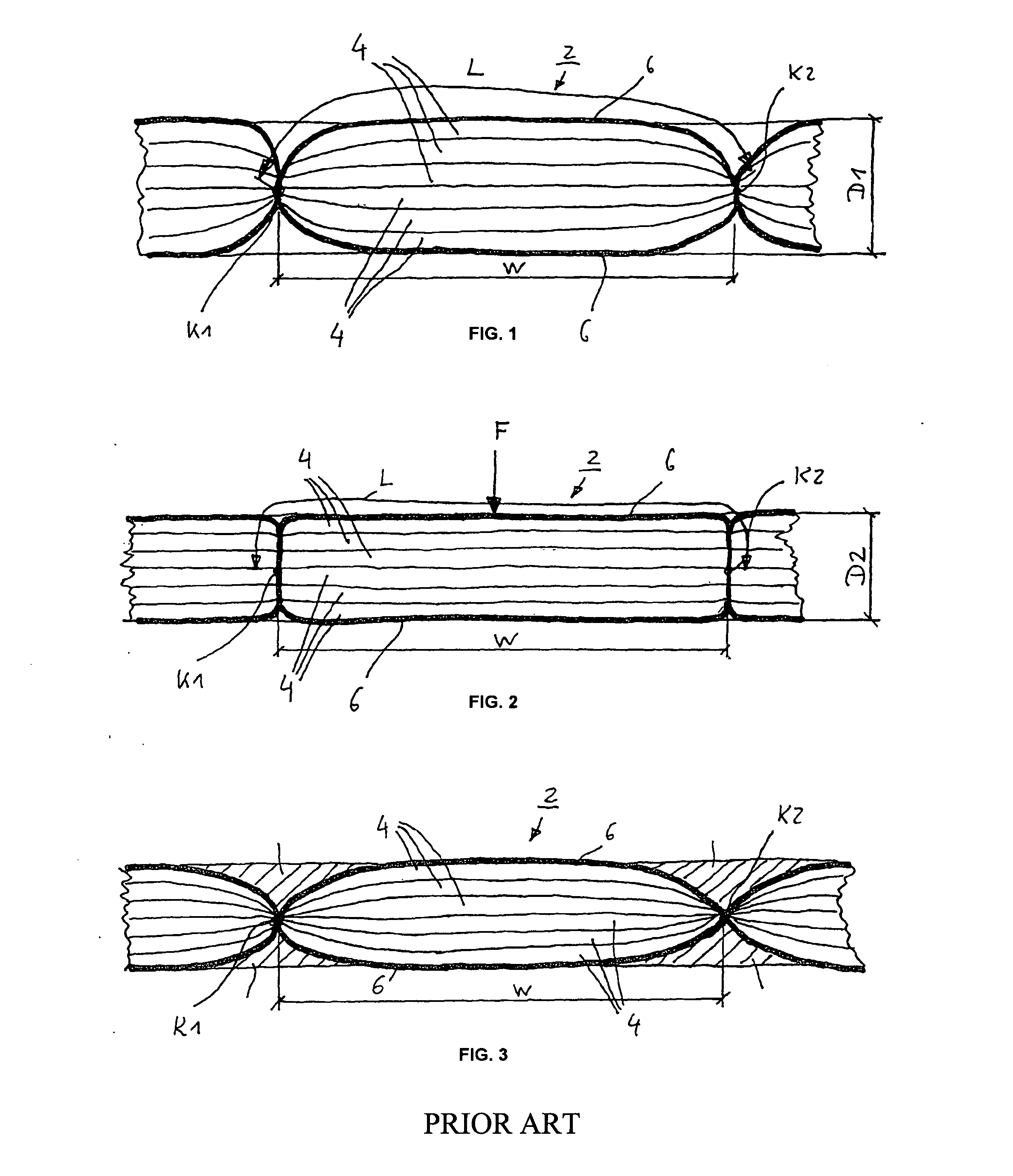
[0019] It is quite evident that here, the seam that is under a prescribed thread tension as a result of the preceding sewing procedure can relax since the original thickness of the reinforcing-fiber preform (or of the preform subunit) diminishes due to the final compacting, even though the length of the sewed thread remains the same. The relaxation effect is naturally further enhanced when a thread having a high relaxation capacity is employed. The result of this relaxation of the seam is that the seam thread in the area of a needle insertion point or of the sewing thread holes created there does not pull together or re-orient itself at all any more, or at least not so markedly. Therefore, unfavorable fiber patterns or even a destruction of the fibers can be effectively prevented.
[0020] Therefore, when one looks at the cross section of the sewed reinforcing-fiber preform, the relaxed seam (which in modern sewing techniques normally consists of a top thread and a bottom thread) acquires a virtually rectangular seam or thread pattern. As a result, in turn, the relatively large funnel-like indentations in the contour of the reinforcing-fiber preform (or in the contour and structure of the preform subunit) that occur in the state of the art can no longer form. Consequently, large, non-reinforced resin accumulations can no longer form during the subsequent injection of the resin. As a result, the strength of the component made of fiber composite material manufactured with the method according to the invention can be considerably increased.
[0021] It should be pointed out that the above-mentioned advantages can also be achieved when a relatively large number of reinforcing-fiber layers is sewed together to form a reinforcing-fiber preform.
[0022] Consequently, the production of a component made of fiber composite material only calls for a relatively small number of reinforcing-fiber preforms (or preform subunits) that can be easily, quickly and efficiently placed into the injection mold one after the other and aligned there. The small number of necessary reinforcing-fiber preforms (or preform subunits) concurrently prevents excessive slipping or shifting of the reinforcing-fiber preforms in the injection mold, which reduces jamming of the preforms due to protruding fiber or preform areas when the injection mold is closed, thus eliminating the need for any reworking of the reinforcing-fiber preforms (or preform subunits). Closing the mold is also facilitated by the compressibility of the reinforcing-fiber preforms (or preform subunits) resulting from the pre-compacting to a pre-compacting size that does not yet constitute the final thickness of the reinforcing material.
[0023] Whereas sewed reinforcing-fiber preforms already compacted to a final size or preforms compacted in a separate process and made of reinforcing-fiber layers impregnated with resin can block the closing of the injection mold since the already final thickness of these elements does not match the closing size of the injection mold due to the manufacturing tolerances that are inevitably present, in the case of the method according to the invention, the placed reinforcing-fiber preforms can still be easily compressed together when the injection mold is closed. This not only allows the injection mold to be closed without any problems and reduces the risk of resin leaking out of the injection mold and of insufficient impregnation of the reinforcing material, but in an advantageous manner, also translates into a dimension-tolerant manufacturing technique without impairing the strength of the component to be made of the fiber composite material.

Problems solved by technology

For instance, it has been found that, during the sewing and compacting, the reinforcing fibers are markedly re-orientated, or even destroyed, which at times drastically reduces the strength of the component made of fiber composite material.
This is considered to be a detrimental aspect, particularly for components made of fiber composite material that are used in the aerospace industry since these have to be designed so as to be not only light in weight but also high in strength.
Moreover, the placement of the numerous reinforcing-fiber preforms into the injection mold—which has to be done in the correct sequence—as well as their alignment are quite complex, tedious and time-consuming.
Moreover, it has been found that problems are often encountered with the closing of the injection mold.
However, if the injection mold is not closed, the risk exists that resin might leak out and that the reinforcing material is not completely impregnated.
In the case of this prior-art method as well, the placement of the numerous reinforcing-fiber preforms into the injection mold in a precisely prescribed sequence is relatively complex, tedious and time-consuming, in addition to which problems are likewise encountered with the closing of the injection mold, thus leading to the above-mentioned disadvantageous consequences.

Method used


Image

  • Method for the production of a fibre composite material component and intermediate product for such a method
  • Method for the production of a fibre composite material component and intermediate product for such a method
  • Method for the production of a fibre composite material component and intermediate product for such a method

Examples


Embodiment Construction

[0035]FIG. 1 shows a schematic cross section of an intermediate product according to the invention in a first stage of the method according to the invention. FIG. 2 shows a schematic cross section through the intermediate product according to the invention as shown in FIG. 1 in a second stage of the method according to the invention. As can be seen in these drawings, the intermediate product according to the invention comprises at least one reinforcing-fiber preform 2 that has several reinforcing-fiber layers 4 that lie on top of one another and that are sewed or joined together by means of a seam 6, in other words, by a sewed thread (here: top and bottom threads). As a result of the sewing, the reinforcing-fiber preform 2 is pre-compacted to a reinforcing-material thickness or to a pre-compacting size D1 at which the seam 6 is under a prescribed thread tension (see FIG. 1). Starting with this pre-compacting size D1 and with the prescribed thread tension, the reinforcing-fiber prefo...


PUM

PropertyMeasurementUnit
tensionaaaaaaaaaa
sizeaaaaaaaaaa
compacting sizeaaaaaaaaaa

Abstract

A method for producing a component made of fiber composite material includes sewing a plurality of reinforcing-fiber layers together using a thread to create a seam and to form at least one reinforcing-fiber preform, wherein the seam has a predetermined thread tension and the sewing pre-compacts the reinforcing-fiber preform to a pre-compacting size. The at least one reinforcing-fiber preform is placed into an injection mold. A final compacting of the reinforcing-fiber preform to a final compacting size is performed by closing the injection mold, wherein the final compacting includes relaxing the thread tension of the seam. A resin is injected into the injection mold and the resin is cured. In addition, an intermediate product includes at least one reinforcing-fiber perform.

Description

FIELD OF THE INVENTION [0001] The present invention relates to a method for the production of a component made of fiber composite material according to the generic part of claim 1 as well as to an intermediate product for such a method. DESCRIPTION OF RELATED ART [0002] A method for the production of a component made of fiber composite material is known in which several reinforcing-fiber layers are sewed and joined together using a thread to form reinforcing-fiber preforms, whereby the seam has a prescribed thread tension, and the reinforcing-fiber preforms are compacted by means of the sewing and a large number of reinforcing-fiber preforms is placed into an injection mold, the injection mold is closed and a resin is injected into the injection mold, after which the resin is cured. In this prior-art method, the reinforcing-fiber preforms are compacted by means of the sewing to, or essentially to, a final compacting size or to a desired thickness. [0003] The above-described method a...

Claims


Application Information

Patent Timeline
Patent Type & Authority Applications(United States)
IPC IPC(8): B29C70/44B32B3/06B29B11/16B29C70/24B29C70/48B29C70/54
CPCB29B11/16B29C70/24Y10T428/24033B29C70/543Y02T50/433B29C70/48Y02T50/40
Inventor NOWACKI, JANWEIMER, CHRISTIAN
Owner AIRBUS HELICOPTERS DEUT GMBH
Learn More