
Fossil fuel combined cycle power generation method

a combined cycle and fuel cell technology, applied in electrochemical generators, machines/engines, mechanical equipment, etc., can solve the problems of limited practical high and low temperature, inefficient use, and maximum thermodynamic efficiency, and achieve the effect of adding energy in the system

Inactive Publication Date: 2007-01-25
UT BATTELLE LLC
View PDF9 Cites 9 Cited by
  • Summary
  • Abstract
  • Description
  • Claims
  • Application Information

AI Technical Summary

Benefits of technology

The patent describes a method and system for converting fuel energy to electricity by using a synthesis gas produced by a reformer. The synthesis gas is then separated into lower molecular weight gases, which are electrochemically oxidized in fuel cells to produce electricity. The system can also include a separator device for dividing the fuel into two gas streams. The method and system can provide higher efficiency and more flexible energy conversion compared to previous methods.

Problems solved by technology

However, these systems depend on obtaining solutions to certain technical problems related to the concept.
For example, these systems do not minimize harmful pollutants or maximize thermodynamic efficiency because they do not provide for recovery of synthesis from CO2, and do not use fuel that passes through the fuel cells unreacted and do not efficiently use “waste heat” generated be the fuel cell stack.
Consequently, since the range of attainable practical high and low temperatures are limited, the maximum possible efficiency derivable from these reversible heat cycles are lower than the Carnot limit.
As a result, practical efficiencies of these closed water or open air cycles cannot be higher than approximately 30 to 35%.

Method used


Image

  • Fossil fuel combined cycle power generation method
  • Fossil fuel combined cycle power generation method
  • Fossil fuel combined cycle power generation method

Examples


Embodiment Construction

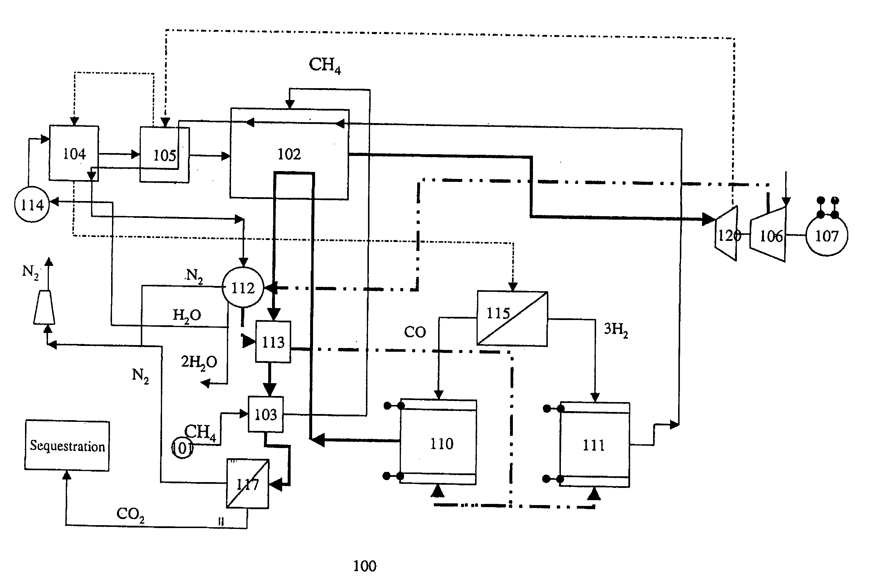
[0028] An apparatus and method for producing a high efficiency electrical power output combines fuel cells and gas turbines. The invention can increase the utilization efficiency of fuels, such as natural gas, in the process of fuel energy conversion to electricity by approximately 20 to 30% compared with existing power systems to approximately 80 to 85%. In addition, the invention produces substantially fewer environmentally harmful emissions compared to other power systems, generating up to approximately three times less harmful emissions compared to existing power systems. Another advantage of the invention is the production of significant quantities of drinking water.

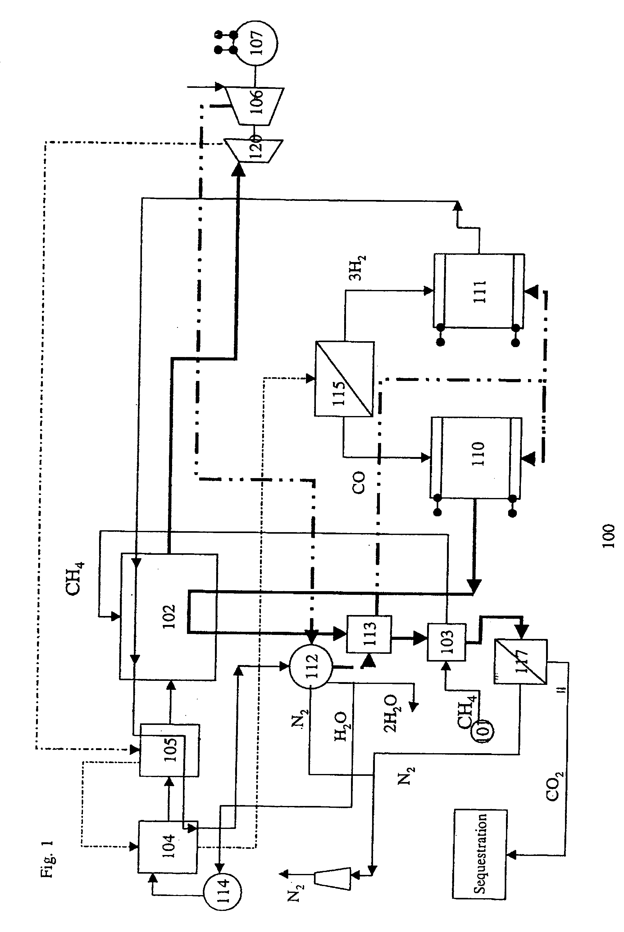
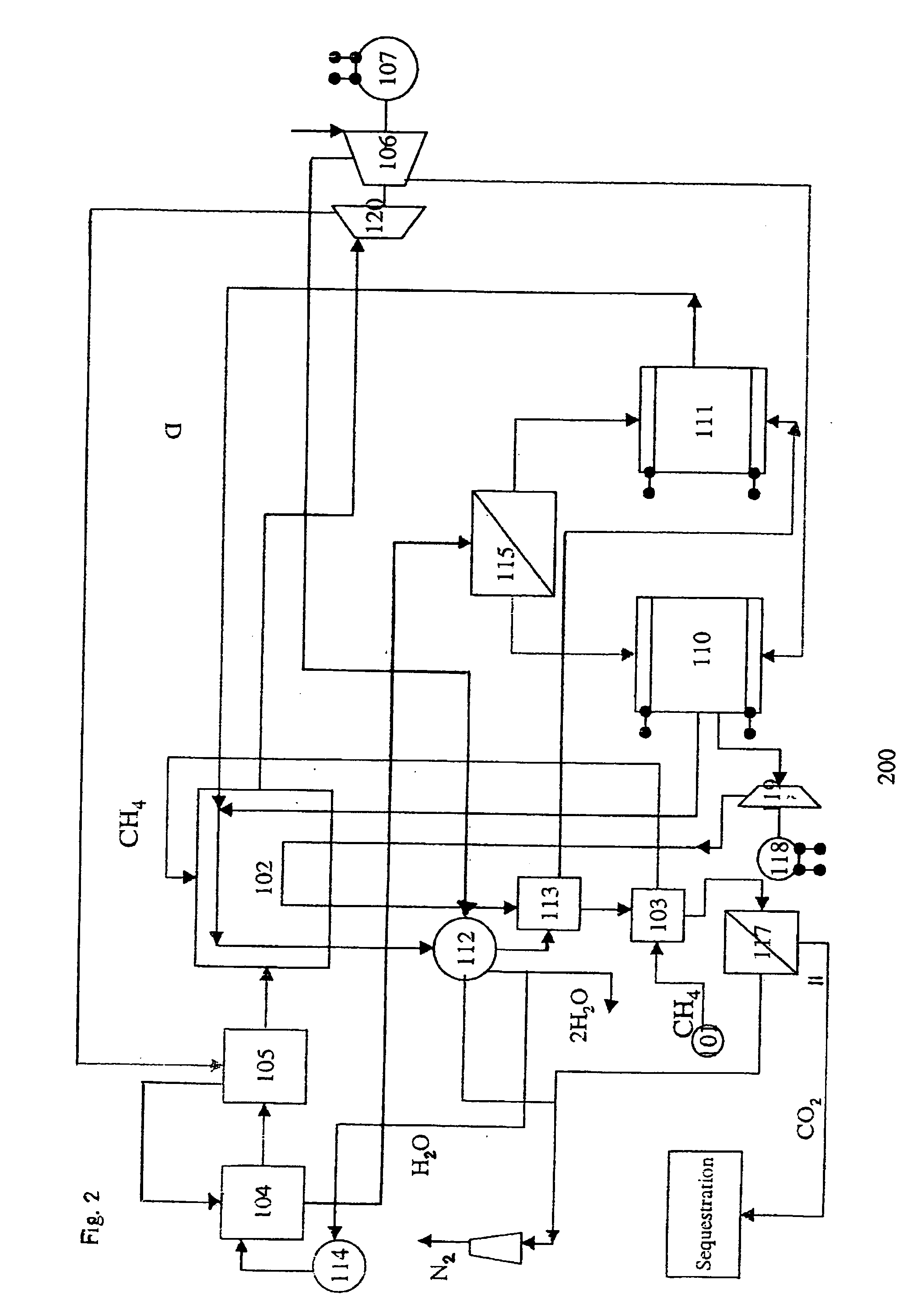
[0029] The apparatus and diagram showing the basic configuration of an embodiment of the invention is shown in FIG. 1. Although specific chemicals, operating conditions and system interconnections are shown therein, the invention is in no way limited to the specific chemicals, operating conditions and system interc...


PUM

PropertyMeasurementUnit
pressureaaaaaaaaaa
pressureaaaaaaaaaa
pressure dropaaaaaaaaaa

Abstract

A method for converting fuel energy to electricity includes the steps of converting a higher molecular weight gas into at least one mixed gas stream of lower average molecular weight including at least a first lower molecular weight gas and a second gas, the first and second gases being different gases, wherein the first lower molecular weight gas comprises H2 and the second gas comprises CO. The mixed gas is supplied to at least one turbine to produce electricity. The mixed gas stream is divided after the turbine into a first gas stream mainly comprising H2 and a second gas stream mainly comprising CO. The first and second gas streams are then electrochemically oxidized in separate fuel cells to produce electricity. A nuclear reactor can be used to supply at least a portion of the heat the required for the chemical conversion process.

Description

CROSS-REFERENCE TO RELATED APPLICATIONS [0001] This application is a divisional of U.S. patent application Ser. No. 09 / 813,714, filed Mar. 21, 2001, entitled “NEW FOSSIL FUEL COMBINED CYCLE POWER SYSTEM”.STATEMENT REGARDING FEDERALLY SPONSORED RESEARCH OR DEVELOPMENT [0002] The United States Government has rights in this invention pursuant to Contract No. DE-AC05-00OR22725 between the United States Department of Energy and UT-Battelle, LLC.FIELD OF THE INVENTION [0003] This invention relates generally to a high efficiency fuel cell / gas turbine combined power generation system and a method of operating such a system. BACKGROUND OF THE INVENTION [0004] New power systems operating on fossil fuels have been under development for several years. These systems are designed to increase efficiency (fuel energy conversion to electricity) and to reduce harmful emissions (NOx, CO, CO2) to the environment. Cogeneration and combined cycle system approaches can increase the efficiency by more than...

Claims


Application Information

Patent Timeline
Patent Type & Authority Applications(United States)
IPC IPC(8): H01M8/04F02C3/28H01M8/06H01M8/24
CPCF02C3/28H01M8/0612Y02E60/50Y02E20/14H01M8/2495
Inventor LABINOV, SOLOMON DAVIDOVICHARMSTRONG, TIMOTHY ROBERTJUDKINS, RODDIE REAGAN
Owner UT BATTELLE LLC
Learn More