
3D velocity modeling, with calibration and trend fitting using geostatistical techniques, particularly advantageous for curved for curved-ray prestack time migration and for such migration followed by prestack depth migration

Inactive Publication Date: 2007-01-25
LEE WOOK B
View PDF31 Cites 44 Cited by
  • Summary
  • Abstract
  • Description
  • Claims
  • Application Information

AI Technical Summary

Benefits of technology

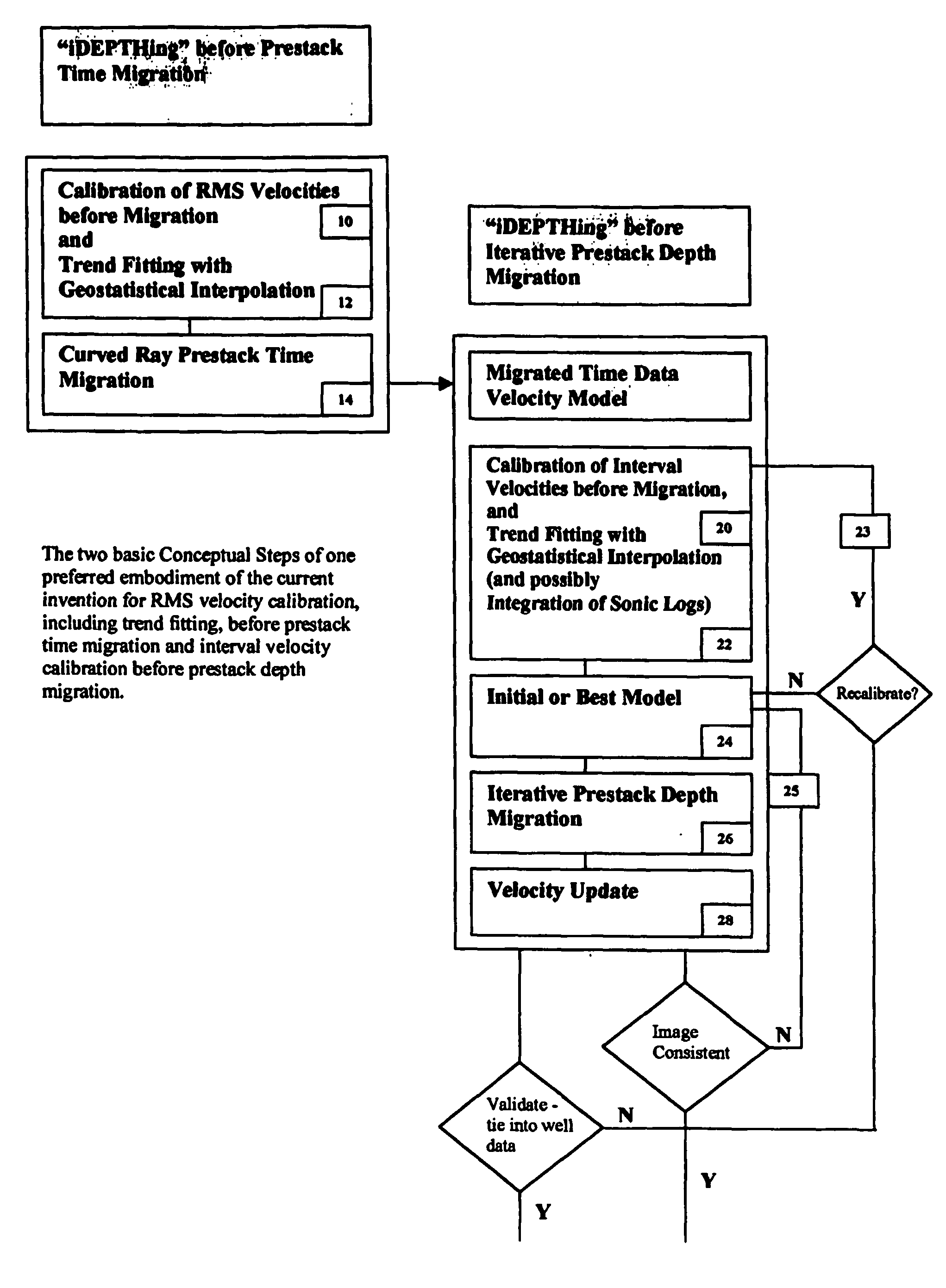
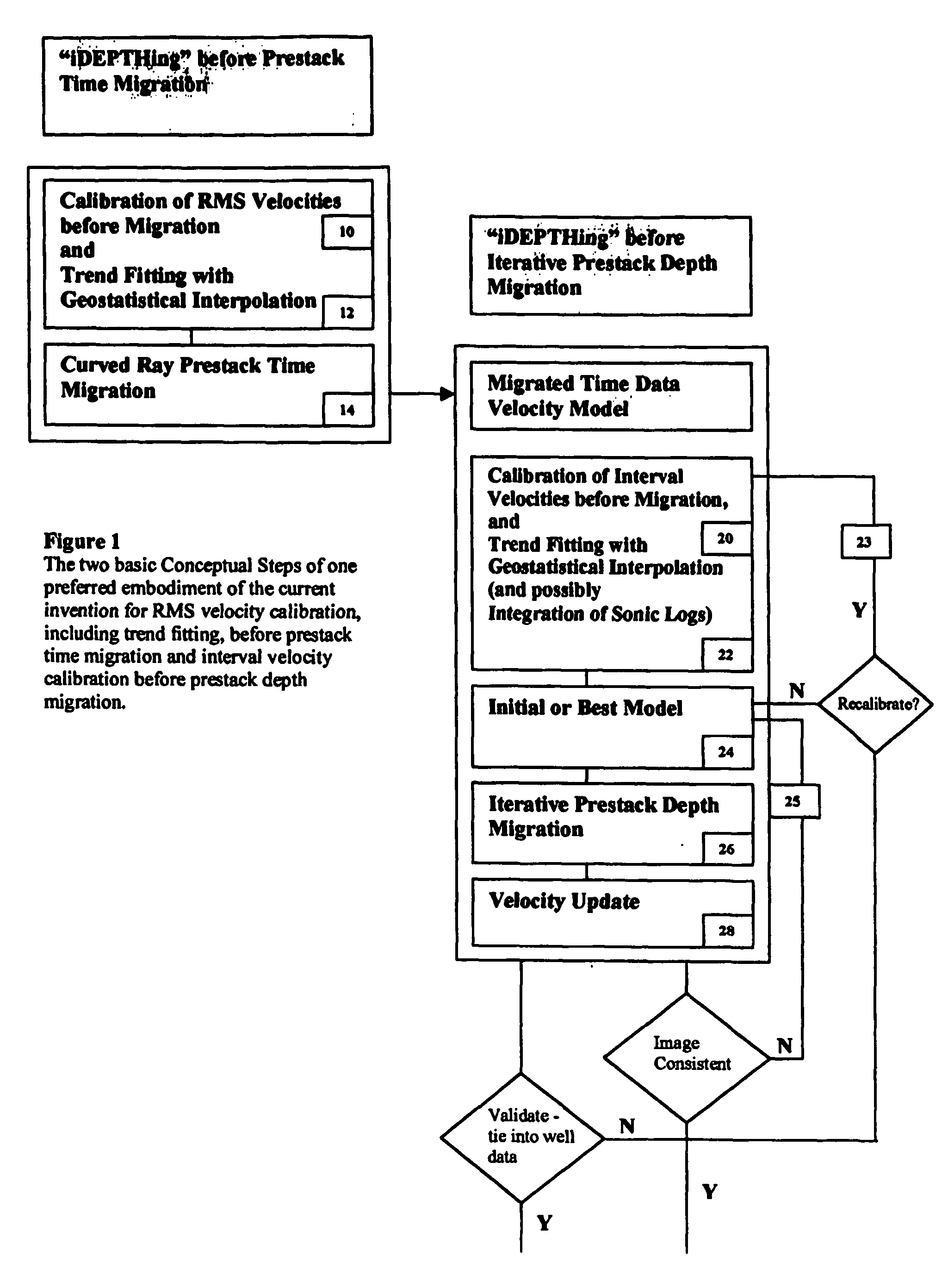
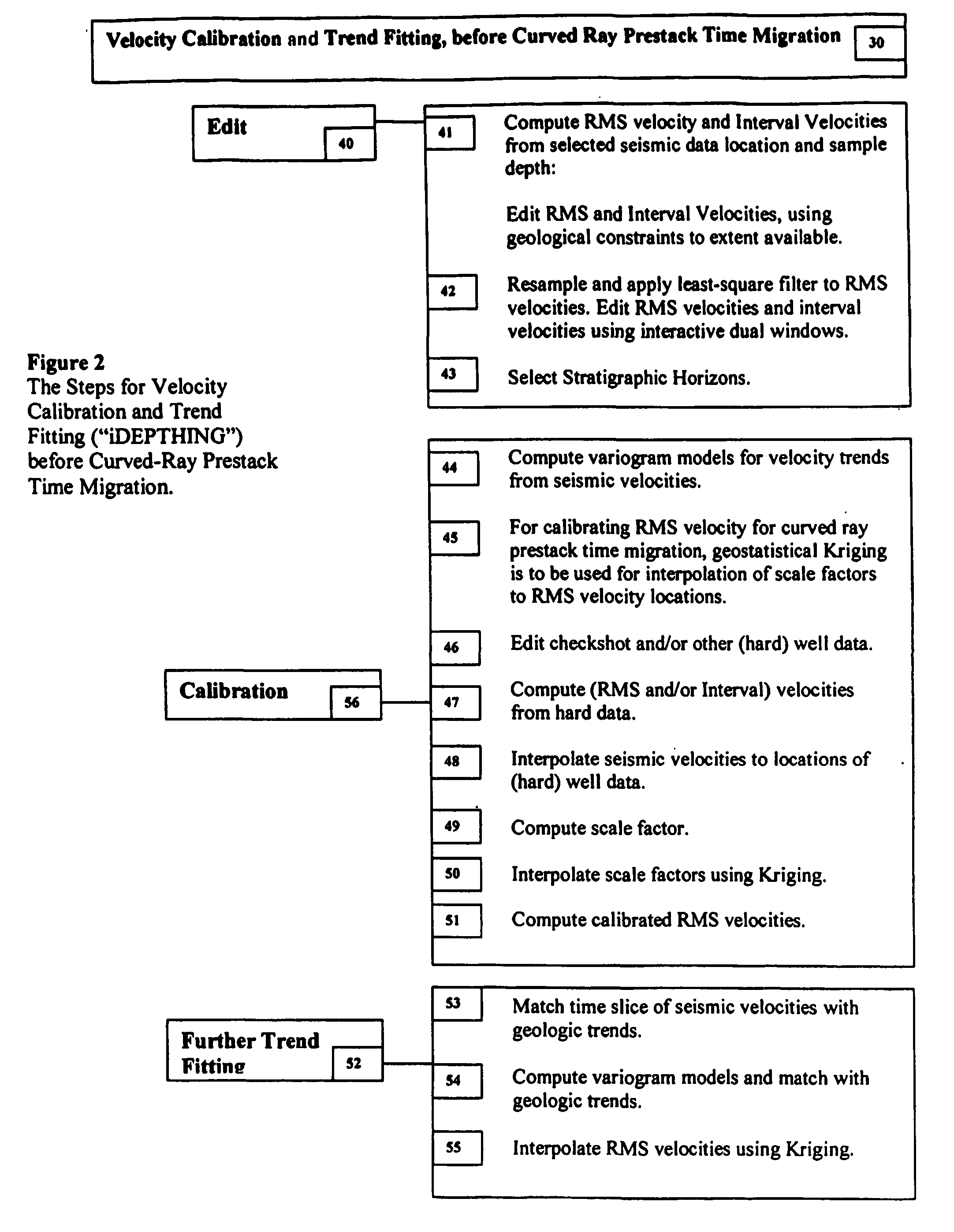
[0027] The instant invention discloses an improved method for constructing a 3D geologically plausible velocity model that has particular value for efficient and accurate prestack imaging. Embodiments of the invention provide: (1) a method for calibrating seismic velocity data, appropriately and effectively taking into account hard data, geological features and utilizing geostatistically sensitive trend fitting (together referred to as “iDEPTHing”) for interpolating, which is particularly valuable for producing RMS velocities for use with curved-ray prestack time migration; (2) a similar method for calibrating and trend fitting (“iDEPTHing”) interval velocities before prestack depth migration, again appropriately and effectively taking into account well (hard) and seismic (soft) data as well as geological features and geostatistical interpolation; and (3) a method for efficient sequential use of iDEPTHing in curved-ray prestack time migration followed by further iDEPTHing and prestack depth migration. Advantages of the embodiments include providing a quick turnaround for prestack time and depth migration images to interpreters and reducing resource-intensive interpretation efforts for 3D seismic data. The invention has significant implications for improving oil and gas exploration and production technologies, including pore pressure prediction, prospect evaluation and seismic attribute analysis.
[0028] Proper calibration and trend fitting of seismic RMS and interval velocities before prestack migration is a key aspect of the instant inventive method, leading to efficient and successful prestack imaging and interpretation of 3D seismic data. Experiment shows that a proper velocity calibration and trend fitting prior to curved-ray presack time migration can provide seismic data with excellent imaging and accurate well ties. Further velocity calibration and trend fitting of interval velocities can provide a further improved geologically plausible velocity model to enhance pre-sack depth migration, both in terms of the speed and the quality of the results.
[0029] Editing seismic velocities using geologic constraints is valuable for effective calibration. Use of stratigraphic surfaces can further play a helpful role in more accurately calibrating seismic velocities. Geostatistical methods (variogram modeling and Kriging) are key factors in interpolating seismic velocities and / or calibration scale factors. A scale of geological heterogeneities is better used for smoothing instead of an arbitrary scale.
[0030] The inventive procedure provides a method of velocity calibration and trend fitting (together referred to herein as “iDEPTHing”) for velocity modeling prior to curved-ray prestack time migration. Such time migration, in turn, offers an improved stepping-stone for efficiently and effectively constructing an accurate 3D velocity model for prestack depth migration.

Problems solved by technology

Time migration is simpler, less resource intensive and considered to be less accurate and less sophisticated.
Historically, the industry has not been bothered to build a sophisticated geologically plausible velocity model prior to prestack time migration, relying instead on simple assumptions deemed to be fitting the technique regarded as less accurate.
The relatively new 3D seismic depth imaging services, techniques that have opened a rapidly growing market in recent years, are at present highly interpretive, quite expensive and very complex processing jobs.
Inconsistencies between processing velocities and the depth tying velocities, however, create formidable challenges at the interpretation stage.
is first guess is going to be wrong. Bu
The iterative technique of depth migration often fails to converge, and it often fails to provide prospects with its economics within reasonable ranges of error for drilling.
And, as Sherwood stated, the initial model is going to be wrong most of the times: the target depth is often wrong based on the result of iteration.
However, considering errors in seismic velocity measurements 5-10%, anisotropy cannot be so easily assumed.
Based on hyperbolic moveout, vertical velocity gradients and velocity trend reversal will be a significant source of errors.
He pointed out that the errors in measuring velocities from semblance clouds make the problem even worse.
This costly method has a fundamental problem of non-uniqueness between layer velocities and layer boundary positions.
This method provides a hand-on interactive tool for velocity editing but does not recognize the importance of velocity calibration.
Inaccurate seismic velocity (soft) data are abundant and reliable well data (hard) data are sparse.
However, it is difficult to access any physical mechanism due to inaccuracies in seismic velocity measurements.
Anisotropy is difficult to measure because it can only be measured in the laboratories.
Excessive smoothing in velocity modeling could be a consequence of embedded velocity errors.
It was detrimental to include erroneous boundaries in a velocity model.

Method used


Image

  • 3D velocity modeling, with calibration and trend fitting using geostatistical techniques, particularly advantageous for curved for curved-ray prestack time migration and for such migration followed by prestack depth migration
  • 3D velocity modeling, with calibration and trend fitting using geostatistical techniques, particularly advantageous for curved for curved-ray prestack time migration and for such migration followed by prestack depth migration
  • 3D velocity modeling, with calibration and trend fitting using geostatistical techniques, particularly advantageous for curved for curved-ray prestack time migration and for such migration followed by prestack depth migration

Examples


Embodiment Construction

Discussion of Terms

Time And Depth Migration

[0051] Seismic migration methods are classified as either depth migration or time 5 migration. Depth migration honors lateral as well as vertical variations, utilizing different assumptions about the physics of seismic wave propagation. Time migration solutions ignore wave-field distortions created by lateral variations in seismic velocities. However simplistic, time migration is widely used because it is less computationally expensive. Curved-ray time migration is a recent advance in prestack time migration, which is sensitive to vertical velocity variations. However, it is only with the relatively recent advent of clustered PC processing that curved-ray prestack time migration has become generally available.

Checkshot Data

[0052] Checkshot is a method of determining an average velocity as a function of depth by lowering a geophone into a hole and recording energy from shots fired from surface shot holes. Checkshot is often run in add...


PUM


Abstract

A method of constructing a 3D geologically plausible velocity model for efficient and accurate prestack imaging wherein embodiments of the invention provide: (1) a method of calibrating velocity functions, appropriately and effectively taking into account well (hard) and seismic (soft) data as well as geological features, and trend fitting (“iDEPTHing”) RMS velocities before curved-ray prestack time migration; (2) a method of calibrating and trend fitting (“iDEPTHing”) interval velocities before prestack depth migration, appropriately and effectively taking into account well (hard) and seismic (soft) data as well as geological features; and (3) a method of constructing a geologically plausible velocity model using the previous steps of velocity calibration and trend fitting RMS and interval velocities, for efficient sequential use in prestack time migration followed by prestack depth migration. Advantages of the embodiments include providing a quick turnaround of prestack time and depth migration to interpreters and cutting back resource-intensive interpretation efforts for 3D seismic data The invention has significant implications for improving aspects of oil and gas exploration and production technologies, including pore pressure prediction, prospect evaluation and seismic attribute analysis.

Description

FIELD OF THE INVENTION [0001] This invention relates to improved methods for building geologically plausible 3D velocity models for use in 3D prestack seismic imaging, in particular for use in curved-ray prestack time migration and in such migration followed by prestack depth migration, and including utilizing geologic data and geostatistical techniques for integrating velocity information derived from seismic data, so called “soft data”, with well data, or so called “hard data”, such as checkshot surveys and sonic logs. BACKGROUND OF THE INVENTION Introduction [0002] In seismic exploration seismic reflection data from subsurface layers are collected by multiple receivers typically at the earth's surface. The more recent 3D seismic acquisitions cover large areas, collecting extensive 3D seismic data for use in subsurface imaging. [0003] Seismic “migration” corrects and improves initial assumptions of near horizontal layering in an attempt to model geophysical realities such as dips...

Claims


Application Information

Patent Timeline
IPC IPC(8): G06G7/48G01V1/30
CPCG01V1/303
Inventor LEE SEISLINK, WOOK B.
Owner LEE WOOK B
Learn More