
Execution device and application program

a technology of execution device and application program, which is applied in the direction of instruments, computing, electric digital data processing, etc., can solve the problems of application programs of the type described above that are not capable of achieving an acceptable level of performance on other apparatuses, application programs may not be executable, and application programs may not achieve an acceptable level of processing performan

Inactive Publication Date: 2007-01-25
PANASONIC CORP
View PDF2 Cites 17 Cited by
  • Summary
  • Abstract
  • Description
  • Claims
  • Application Information

AI Technical Summary

Benefits of technology

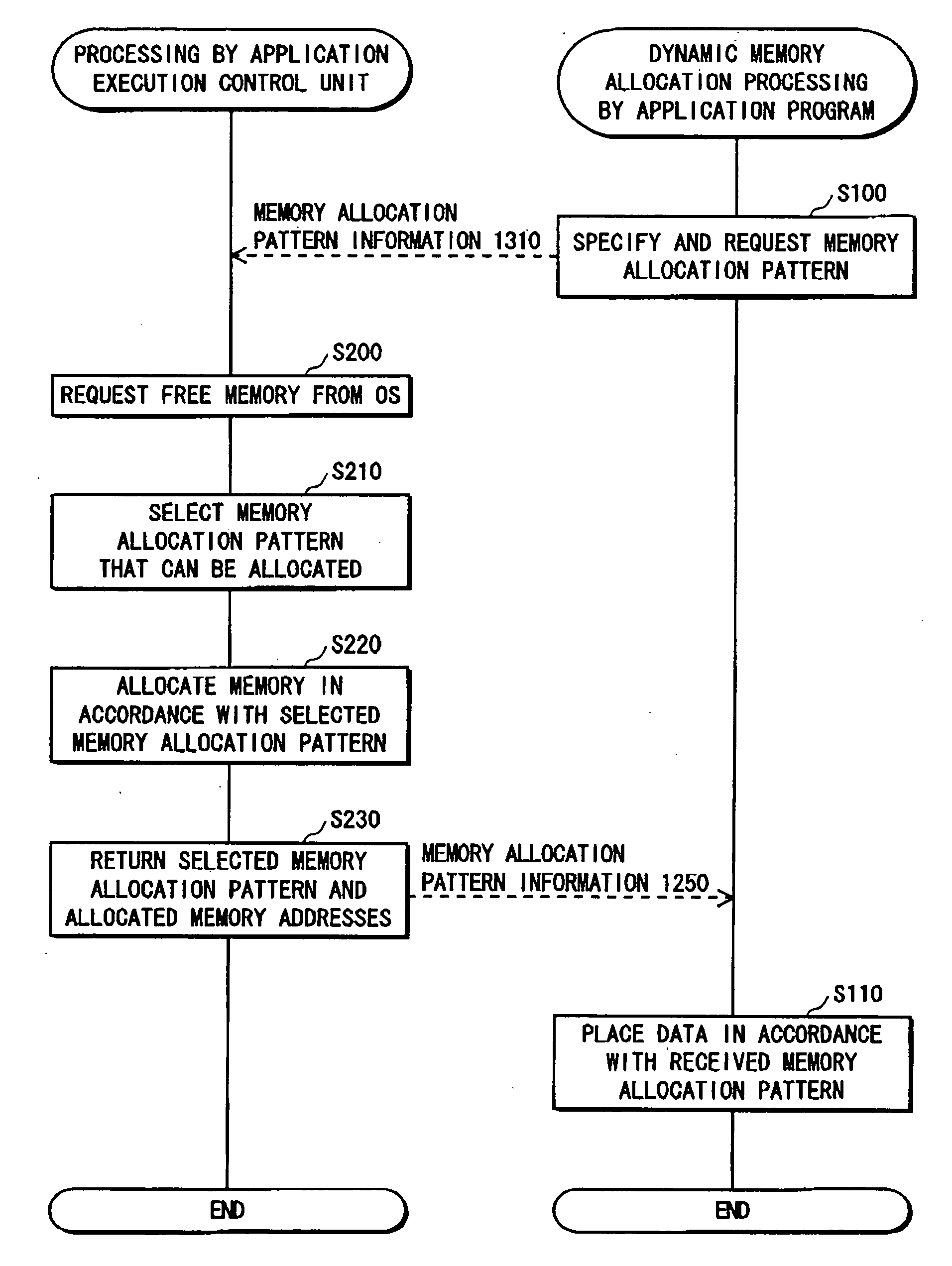
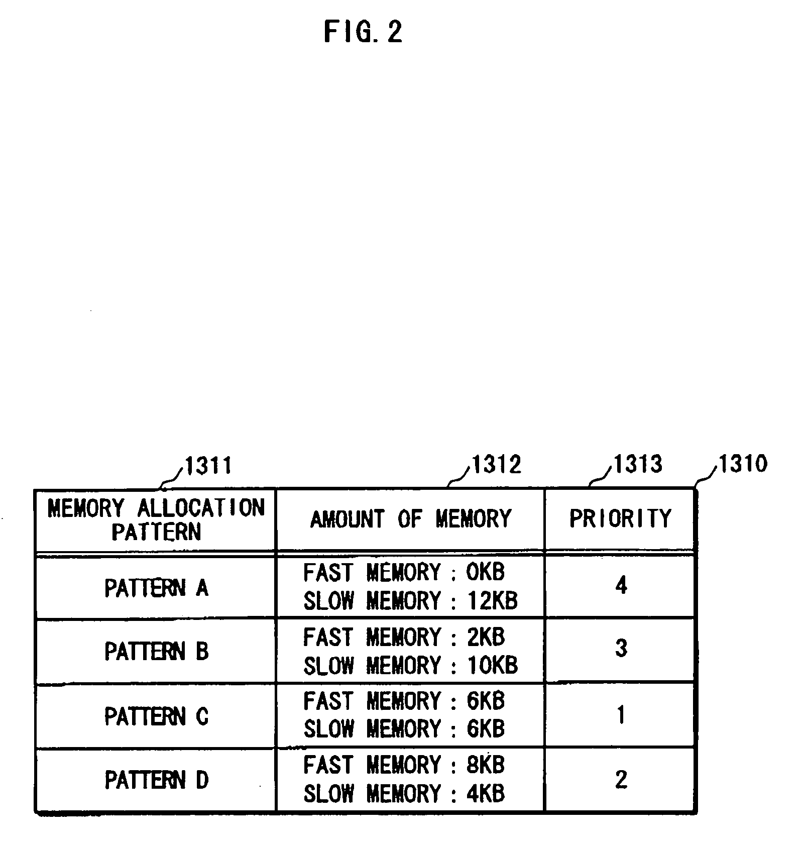
"The present invention provides an application program and an execution device that can achieve a satisfactory level of performance regardless of different hardware structures and environments. The execution device includes a storage unit that stores a plurality of memory allocation patterns, a selection unit that selects one of the patterns, an allocation unit that allocates memory areas based on the selected pattern, and an execution unit that executes the application program using the allocated memory areas. The application program includes a procedure for each memory allocation pattern to perform processing in accordance with the pattern. The execution device can acquire information about free areas of memory and place data objects in the allocated memory areas based on their access speeds. The invention aims to provide an application program and an execution device that can achieve a high level of performance on different hardware structures and environments."

Problems solved by technology

However, as a result of being developed for the system of a specific apparatus, it is often the case that application programs of the type described above are not capable of achieving an acceptable level of performance on other apparatus.
Thus, in an unaltered form, the application program may not be executable due to a lack of memory resources.
Even when executable, the application program may not achieve an acceptable level of processing performance when the amount of available memory is small.
Another possibility is that the required level of processing performance can be achieved, but the application program cannot use the memory resources of the apparatus effectively, and is unable to achieve a level of performance commensurate with the amount of available memory.

Method used


Image

  • Execution device and application program
  • Execution device and application program
  • Execution device and application program

Examples


first embodiment

Construction

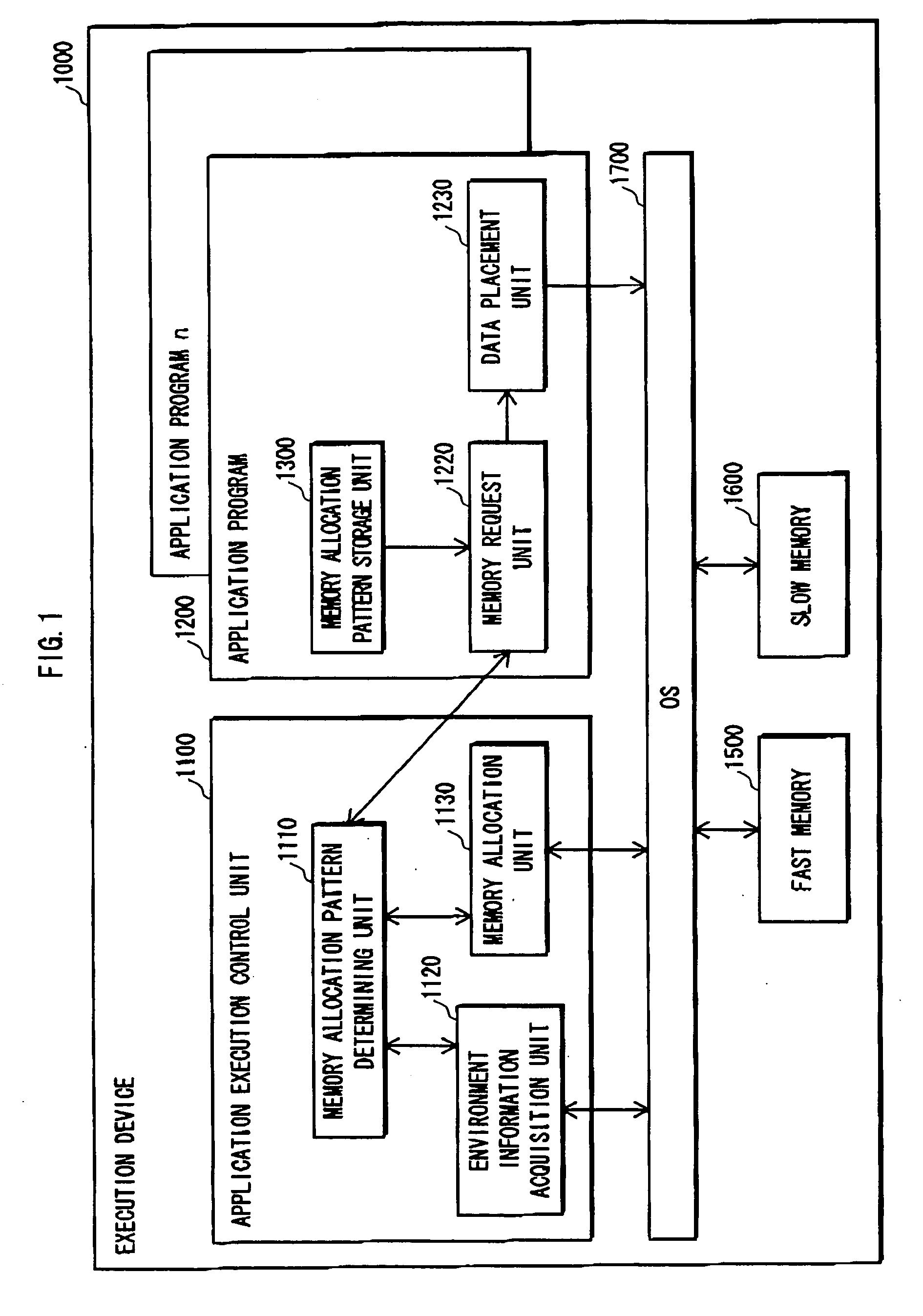
[0057] The following describes the execution device of the first embodiment of the present invention with reference to FIG. 1.

[0058] In the description, it is assumed that the program of the present invention is already loaded in the execution device.

[0059]FIG. 1 is a functional block diagram showing the construction of the execution device.

[0060] The execution device 1000 is constructed from an application execution control unit 1100, an application program 1200, a fast memory 1500, a slow memory, and an OS 1700.

[0061] The OS 1700 is basic software that manages the various resources of the execution device, and manages execution of the program. For example, the OS performs processing to allocate and free memory for the application program.

[0062] The fast memory 1500 and the slow memory 1600 are memories with different access speeds. These memories are included in the functional block diagram of FIG. 1 to show the interaction between the memories and the OS 1700. ...

second embodiment

Differences from First Embodiment

[0122] The following describes the second embodiment of the present invention. According to the first embodiment described above, all the allocation patterns require the same amount memory. According to the second embodiment, however, each memory allocation pattern requires a different amount memory.

[0123] Since the overall amount of required memory is variable, an advantageous effect is archived that a wider variety of devices is able to run the application program.

[0124] According to the second embodiment, a mechanism to select data objects to be placed in memory is added to more suitably manage the case where the amount of allocated memory is small.

Operation

[0125] The following describes the execution device of the second embodiment of the present invention using FIG. 6.

[0126]FIG. 6 is a functional block diagram showing the construction of an execution device of the second embodiment.

[0127] This execution device differs from the one of th...


PUM


Abstract

An execution device includes one or more memories for use when executing an application program. The execution device selects one of a plurality of patterns relating to memory areas required for executing the application program, secures memory areas in the one or more memories in accordance with the selected pattern, and executes using the secured memory areas.

Description

BACKGROUND OF THE INVENTION [0001] (1) Field of the Invention [0002] The present invention relates to an application program execution device, and especially to a technology for using memory effectively. [0003] (2) Description of the Related Art [0004] In recent years, an increasing number of household appliances and audio / video apparatus are equipped with a computer system. [0005] Regarding the computer systems of such mass-produced appliances and apparatus, it is generally the case that the processing power of the processor and amount of memory are limited due cost requirements. In such computer systems, the hardware and OS (Operation System) are usually optimized to include only those functions used by the application program. [0006] One method for optimizing the allocation of memory resources is described in Patent Document 1. The disclosed technology finds optimum memory allocation in advance by running a simulation of the program on a model of the system. [0007] To secure the ...

Claims


Application Information

Patent Timeline
Patent Type & Authority Applications(United States)
IPC IPC(8): G06F9/45
CPCG06F9/5016
Inventor MASUDA, YUKIO
Owner PANASONIC CORP
Learn More