Ultrasonic sensor unit and electronic device

a technology of ultrasonic and sensor unit, applied in the direction of mechanical vibration separation, instruments, and using reradiation, can solve the problem of not being able to demonstrate the maximum level of performance in each type of sensor

Active Publication Date: 2010-08-12
SEIKO EPSON CORP
View PDF7 Cites 31 Cited by
  • Summary
  • Abstract
  • Description
  • Claims
  • Application Information

AI Technical Summary

Benefits of technology

[0008]The present invention was developed in view of such drawbacks, and an object of the present invention is to provide an ultrasonic sensor unit whereby the maximum level of performance can be demonstrated both during transmission and reception of ultrasonic waves.
[0010]According to the ultrasonic sensor unit of the first aspect, the fact that an ultrasonic transmission sensor array and an ultrasonic reception sensors are independently provided means that it is possible to obtain a structure provided with ultrasonic transmission sensors that output a high acoustic pressure, and ultrasonic reception sensors that have excellent reception sensitivity, by forming the ultrasonic transmission sensor array and the ultrasonic reception sensors according to conditions optimal for each type of sensor. It is thereby possible to provide a highly reliable ultrasonic sensor unit that is capable of demonstrating the maximum level of performance both during transmission and reception of ultrasonic waves. Since the ultrasonic reception sensor array and the ultrasonic transmission sensor array are also bonded together, the rigidity of the sensor array is increased, and reliability during transmission and reception of ultrasonic waves can be enhanced.
[0012]According to this configuration, the fact that the ultrasonic transmission sensors are regularly arranged means that the ultrasonic transmission sensor array can transmit ultrasonic waves at a high acoustic pressure. Since the ultrasonic reception sensors are also regularly arranged, the ultrasonic reception sensor array can receive with excellent sensitivity the ultrasonic waves transmitted from the ultrasonic transmission sensor array.
[0014]According to such a configuration, the fact that piezoelectric or capacitive sensors are used makes it possible to enhance the degree of freedom in the design of the ultrasonic transmission sensor array and the ultrasonic reception sensor array. It is thereby possible to provide an ultrasonic sensor unit that is capable of demonstrating the maximum level of performance under the desired conditions.
[0016]According to such a configuration, the fact that each of the ultrasonic transmission sensors and the ultrasonic reception sensors are provided in an optimal number allows satisfactory characteristics to be obtained both during transmission and reception of ultrasonic waves.

Problems solved by technology

However, since the optimum diaphragm structures of sensors for ultrasonic transmission and sensors for ultrasonic reception are not the same, the maximum level of performance cannot be demonstrated in each type of sensor.

Method used


Image

  • Ultrasonic sensor unit and electronic device
  • Ultrasonic sensor unit and electronic device
  • Ultrasonic sensor unit and electronic device

Examples


first embodiment

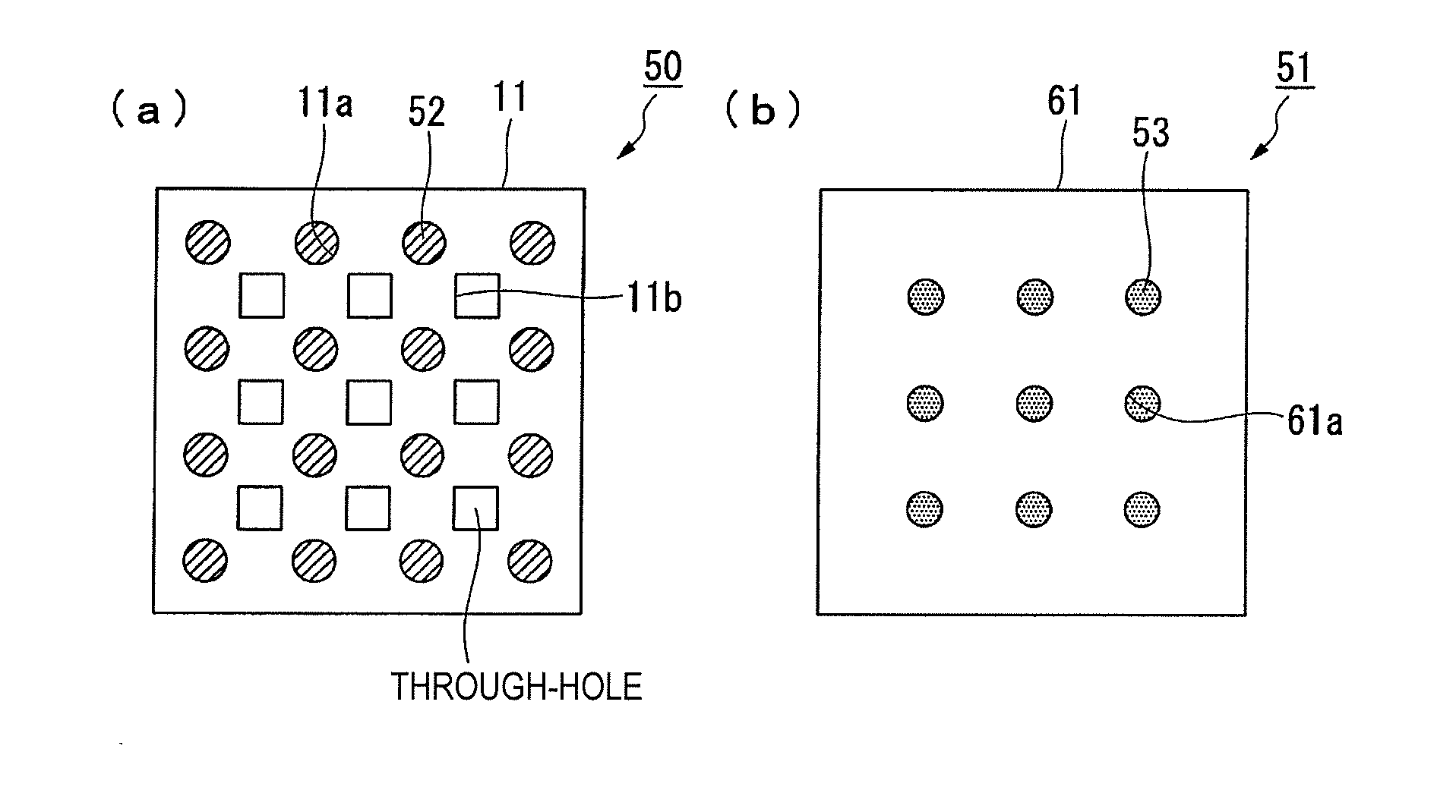
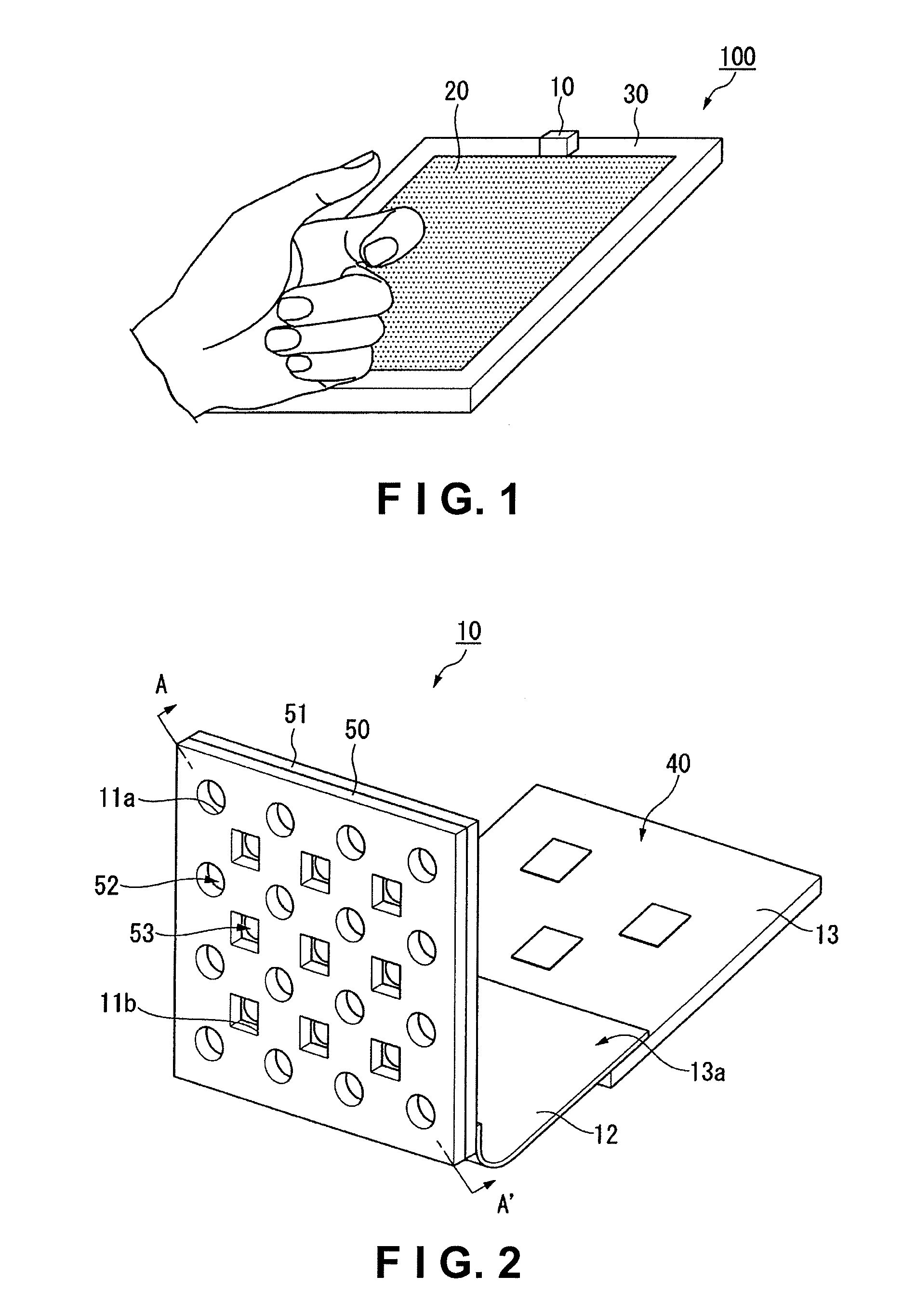
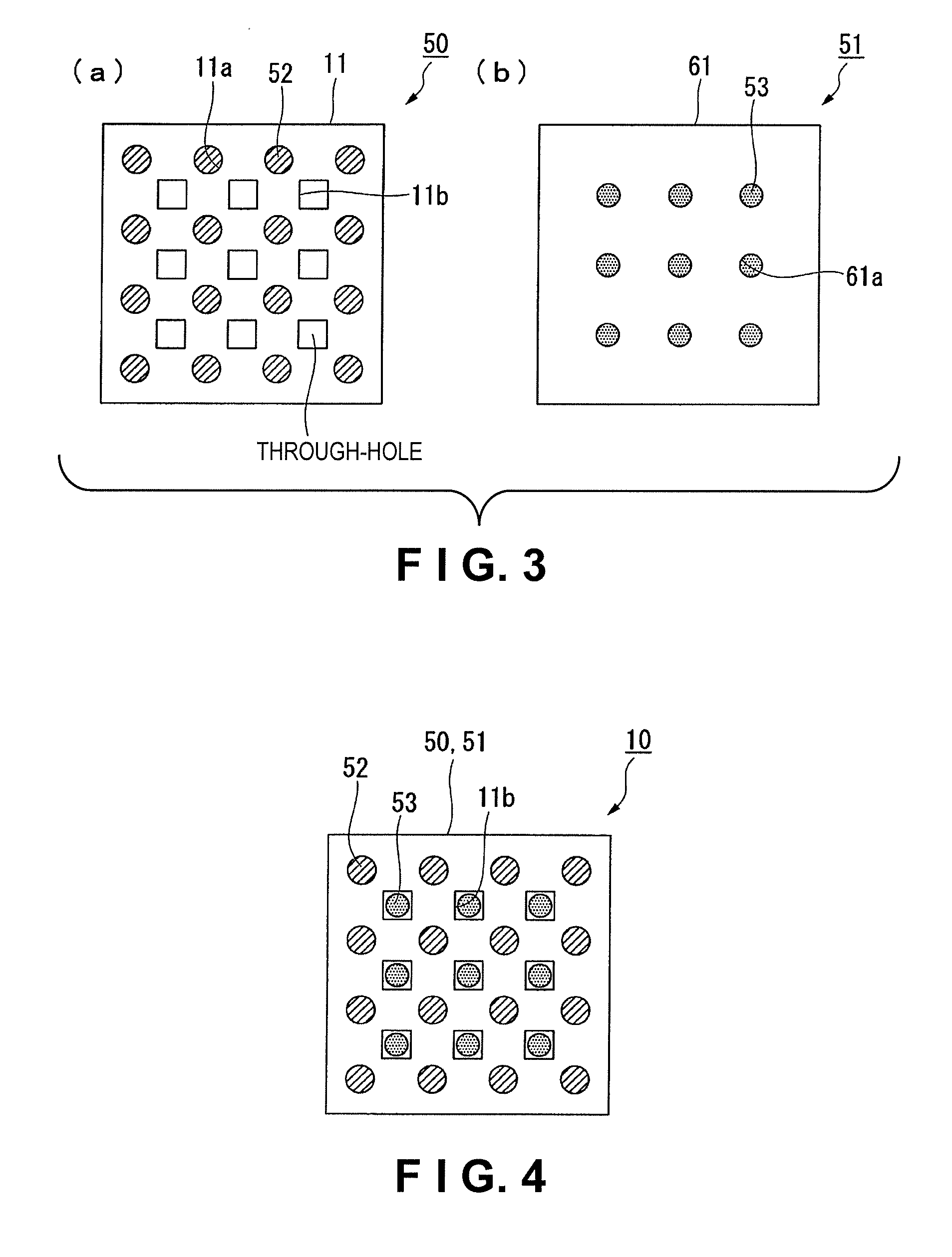
[0030]FIG. 1 is a schematic perspective view showing the structure of the PDA of the present embodiment. FIG. 2 is a schematic perspective view showing the structure of the ultrasonic sensor unit provided to the PDA of the present embodiment. FIG. 3(a) is a view showing the planar structure of an ultrasonic transmission sensor array as a constituent element of the ultrasonic sensor unit; and FIG. 3(b) is a view showing the planar structure of an ultrasonic reception sensor unit as a constituent element of the ultrasonic sensor unit. FIG. 4 is a view showing the planar structure of the ultrasonic sensor array. FIG. 5 is a schematic system structure view showing the structure of the control unit of the ultrasonic sensor unit of the present embodiment. In FIG. 5, the structure for applying a constant voltage to the second lower electrode described hereinafter is not shown.

[0031]In the PDA 100 of the present embodiment as shown in FIG. 1, a display unit 20 is provided to a main body 30....

second embodiment

[0080]The ultrasonic sensor unit according to a second embodiment of the present invention will next be described. The ultrasonic sensor unit of the present embodiment differs from the ultrasonic sensor unit of the first embodiment with regard to the arrangement structure of the ultrasonic sensors, and the other aspects of the two embodiments are the same. The same reference symbols are therefore used to refer to members that are the same as those of the first embodiment, and no detailed description of such members will be given.

[0081]FIG. 9(a) is a view showing the planar structure of the ultrasonic transmission sensor array of the present embodiment, and FIG. 9(b) is a view showing the planar structure of the ultrasonic reception sensor array of the present embodiment. FIG. 10 is a view showing the planar structure of the ultrasonic sensor unit of the present embodiment.

[0082]As shown in FIG. 9(a), a plurality of ultrasonic transmission sensors 52 is arranged in concentric circles...


PUM


Abstract

An ultrasonic sensor unit includes an ultrasonic transmission sensor array having a plurality of ultrasonic transmission sensors configured and arranged to transmit ultrasonic waves, and an ultrasonic reception sensor array having a plurality of ultrasonic reception sensors configured and arranged to receive the ultrasonic waves. The ultrasonic reception sensor array re coupled to the ultrasonic transmission sensor array so that the ultrasonic transmission sensors and the ultrasonic reception sensors do not overlap in planar view. One of the ultrasonic transmission sensor array and the ultrasonic reception sensor array include a plurality of through-holes through which one of the ultrasonic transmission sensors and the ultrasonic reception sensors provided in the other of the ultrasonic transmission sensor array and the ultrasonic reception sensor array are exposed.

Description

CROSS-REFERENCE TO RELATED APPLICATIONS[0001]This application claims priority to Japanese Patent Application No. 2009-026365 filed on Feb. 6, 2009. The entire disclosure of Japanese Patent Application No. 2009-026365 is hereby incorporated herein by reference.BACKGROUND[0002]1. Technical Field[0003]The present invention relates to an ultrasonic sensor unit.[0004]2. Related Art[0005]Ultrasonic sensors are used to measure distance to a target object, measure flow rates, perform nondestructive testing of ducts, and to conduct numerous other types of measurement or detection. A diaphragm-type ultrasonic sensor is known as a conventional example of such an ultrasonic sensor. In this type of ultrasonic sensor, a PZT ceramic thin film layer flanked by two electrodes is formed on one side of a diaphragm, and the electrical signals outputted from the electrodes are used to detect ultrasonic waves (see Japanese Laid-Open Patent Publication No. 2005-49301, for example).[0006]An ultrasonic sens...

Claims


Application Information

Patent Timeline
Patent Type & Authority Applications(United States)
IPC IPC(8): H04R17/00
CPCG01S7/52079G01S15/8925G06F3/044G06F3/017G06F1/1626G06F3/0445
Inventor NAKAMURA, TOMOAKI
Owner SEIKO EPSON CORP
Why Eureka
Try Eureka