Vapor chamber and manufacturing method thereof

a manufacturing method and technology of vapor chamber, applied in the field of cooling apparatuses, can solve the problems of reducing the transferring effect of the vapor chamber, adversely obstructing the thermal transmission pathway, and reducing the reliability of fabrication, so as to facilitate the movement of the working fluid, improve the thermal transmission pathway, and improve reliability

Inactive Publication Date: 2007-02-01
DELTA ELECTRONICS INC
View PDF12 Cites 19 Cited by
  • Summary
  • Abstract
  • Description
  • Claims
  • Application Information

AI Technical Summary

Benefits of technology

[0011] According to the method for manufacturing a vapor chamber, the top and bottom plates can be integrally formed as a single piece, rather than using conventional welding method so as to avoid long welding path and improve reliability. Further, as continuous capillary structure facilitates movement of the working fluid, thermal transmission pathway is improved, as compared with the discontinuous capillary structure of conventional vapor chambers.
[0012] The method for manufacturing vapor chamber of the invention is suitable for single sintering process, wherein the dimension of the vapor chamber is adjustable by demand, thereby reducing mold cost and simplifying manufacturing processes. In summary, the method for manufacturing vapor chamber is cheap and flexible, producing various shapes of vapor chambers.

Problems solved by technology

However, the disconnection area 141 adversely obstructs the thermal transmission pathway and reduces transferring effect of the vapor chamber.
As conventional vapor chambers are produced by welding two plates, the long welding path may reduce fabrication reliability and the capillary structures cannot be continuously formed on the inner surfaces of the two plates.
As conventional welding fabrication requires many parts and complex molding technologies, production costs are potentially increased.
Further, since the top and bottom plates must be produced individually with specific profiles, it is difficult to produce the two plates of different dimensions simultaneously during a single sintering process.

Method used


Image

  • Vapor chamber and manufacturing method thereof
  • Vapor chamber and manufacturing method thereof
  • Vapor chamber and manufacturing method thereof

Examples


first embodiment

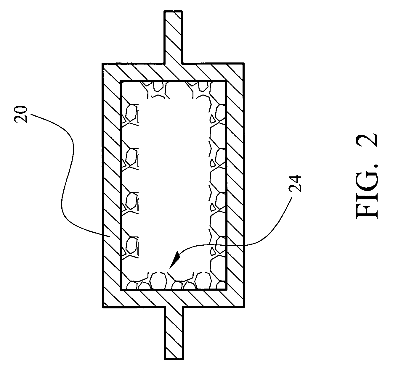
[0017]FIG. 2 is a sectional view of a vapor chamber 2. The vapor chamber 2 includes a hollow tube 20 and a continuous capillary structure 24 disposed on the inner surface of the hollow tube 20.

second embodiment

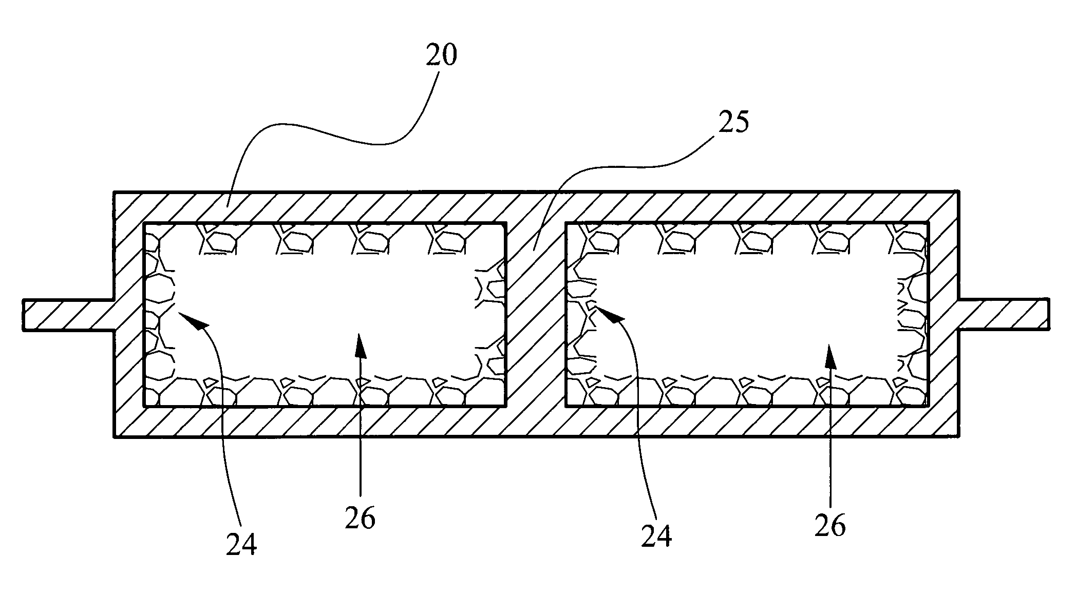
[0018]FIG. 3 is a sectional view of a vapor chamber 3. Elements corresponding to those of FIGS. 2 and 3 share the same reference numerals, and explanation thereof is omitted for simplification of the description. Unlike FIG. 2, here, the hollow tube 20 is separated by a partition 25 into a plurality of closed rooms 26, and the capillary structure 24 is formed on the inner surfaces of the hollow tube 20 and the surface of the partition 25.

[0019] In a method for manufacturing vapor chambers, a hollow tube is integrally formed by copper extrusion or drawing. The hollow tube may be circular, elliptical, half-circular, rectangular, triangular, square, trapezoid, pentagonal, hexagonal, octagonal, equilateral or inequilateral in cross-section. The hollow tube is made of aluminum, copper, titanium, molybdenum, or a metal with a high thermal conductivity. Subsequently, a capillary structure is formed on the inner surface of the hollow tube and the surface of the partition 25 by sintering. Sp...


PUM

PropertyMeasurementUnit
thermal conductivityaaaaaaaaaa
capillary structureaaaaaaaaaa
structureaaaaaaaaaa

Abstract

A vapor chamber applied to an electronic device generating heat is provided. The vapor chamber includes a hollow tube and a capillary structure, which is continuously formed on the inner surface of the hollow tube. The method for manufacturing the vapor chamber includes providing a hollow tube, forming the capillary structure on the inner surface of the hollow tube, filling a working fluid into the tube, and finally evacuating the hollow tube and sealing the other end of the tube, so as to provide better thermal transferring effect.

Description

[0001] This non-provisional application claims priority under U.S.C.§ 119(A) on patent application No. 094125806, filed in Taiwan, Republic of China on Jul. 29, 2005, the entire contents of which are hereby incorporated by reference. BACKGROUND OF THE INVENTION [0002] 1. Field of the Invention [0003] The invention relates in general to cooling apparatuses and in particular to a method for manufacturing vapor chambers. [0004] 2. Description of the Related Art [0005] With progress in IC fabrication, while the number of transistors per unit area within an electronic component has greatly increased, more heat is generated during its operation. Heat pipes are widely used in heat dissipation of electronic devices because its simple structure and high efficiency. The heat pipes dissipate heat by using a working fluid continuously transferring between the liquid phase and the gas phase so as to carry heat away from the heat source. [0006] Vapor chambers are a specific type of heat pipes, ap...

Claims


Application Information

Patent Timeline
Patent Type & Authority Applications(United States)
IPC IPC(8): B23P6/00
CPCB23P15/26B23P2700/09F28D15/0233F28D15/0283Y10T29/49353H01L23/427H01L2924/0002F28D15/046H01L2924/00
Inventor CHUANG, MING-TECHENG, CHIN-MINGLIN, CHI-FENGCHEN, CHIN-MING
Owner DELTA ELECTRONICS INC
Why Eureka
Try Eureka