PTO assembly for a gas turbine engine

a gas turbine and assembly technology, applied in the direction of hot gas positive displacement engine plants, machines/engines, engine fuctions, etc., can solve problems such as unsatisfactory engine efficiency

Inactive Publication Date: 2007-02-01
GENERAL ELECTRIC CO
View PDF10 Cites 95 Cited by
  • Summary
  • Abstract
  • Description
  • Claims
  • Application Information

AI Technical Summary

Benefits of technology

[0006] According to another aspect of the invention, a gas turbine engine includes a first compressor connected to a first turbine by a first drive shaft; a second compressor connected to a second turbine by a second drive shaft which is concentric to the first drive shaft; a first ring gear coupled to the first drive shaft; a first bevel gear engaged with the first ring gear and connected to a power take off shaft; a second ring gear coupled to the second drive shaft; a second bevel gear engaged with the second ring gear; and a one-way clutch coupling the second bevel gear to the power take off shaft. The one-way clutch is configured to permit free rotation of the second bevel gear relative to the power take off shaft in a first direction, and to prevent relative rotation of the second bevel gear relative to the power take off shaft in the opposite direction.

Problems solved by technology

It is not ideal in terms of engine efficiency to supply the PTO loads through the engine core rather than through the low pressure system.
Unfortunately, the best means of starting the engine is via the high pressure shaft.

Method used


Image

  • PTO assembly for a gas turbine engine
  • PTO assembly for a gas turbine engine
  • PTO assembly for a gas turbine engine

Examples


Embodiment Construction

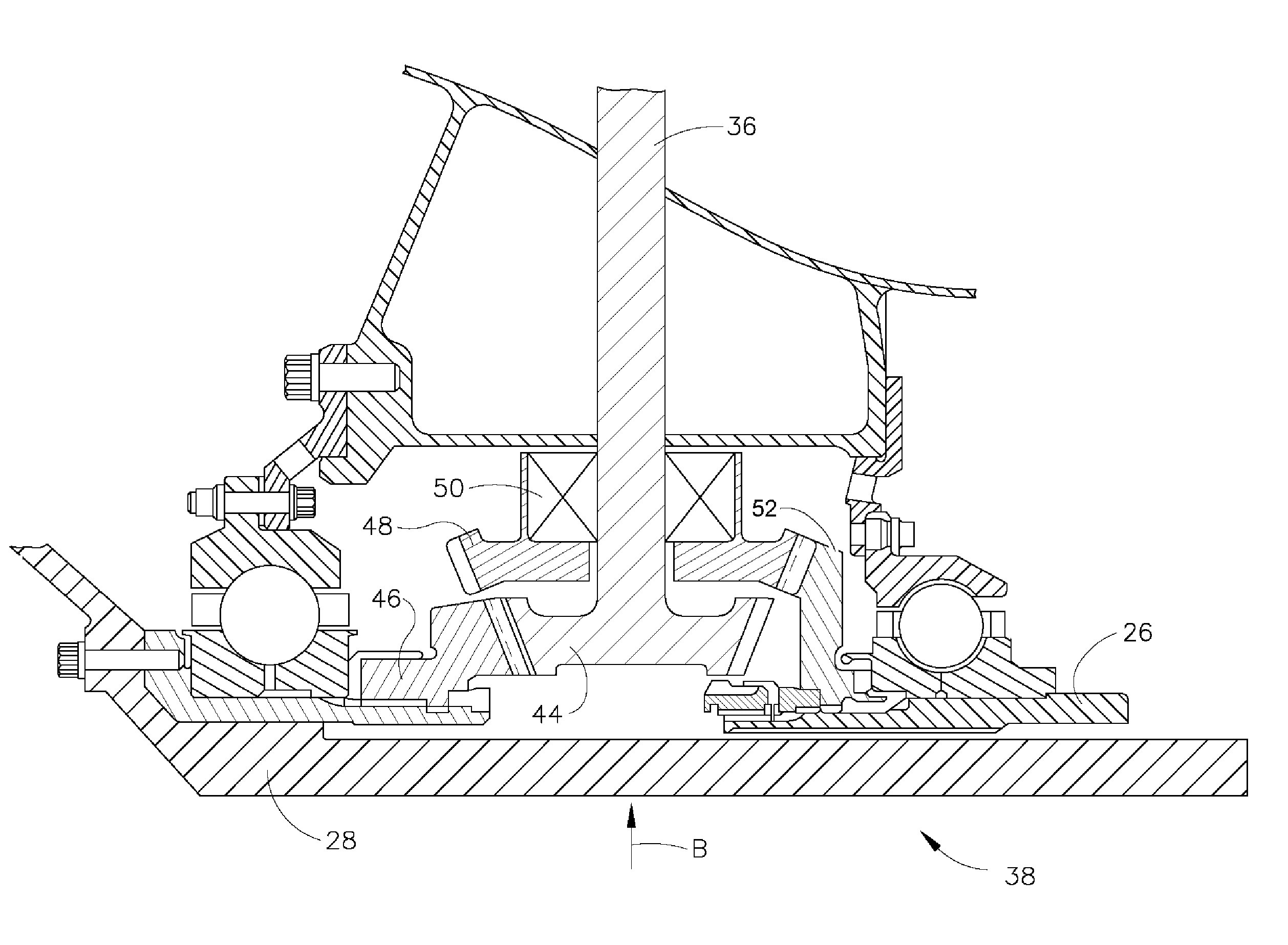
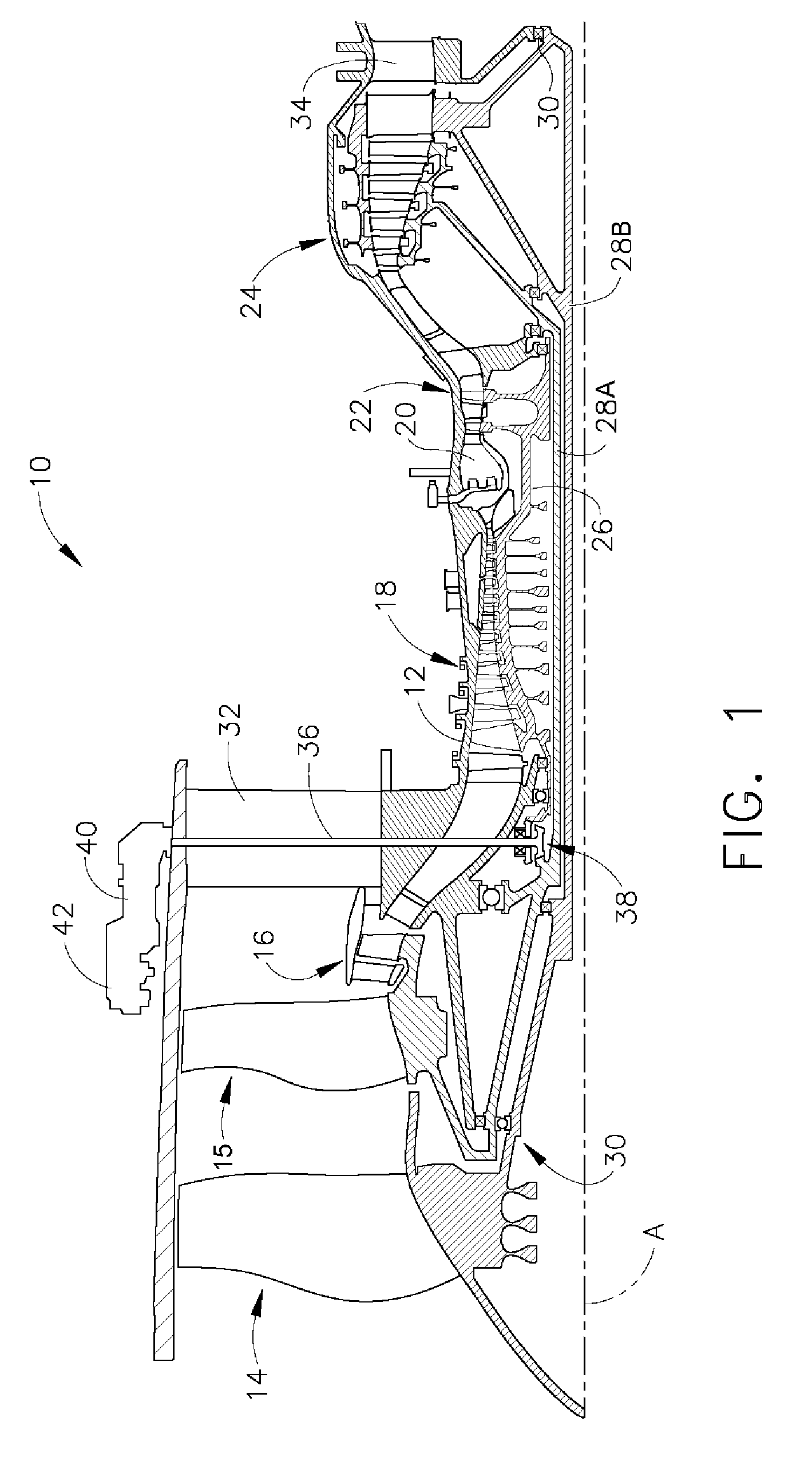
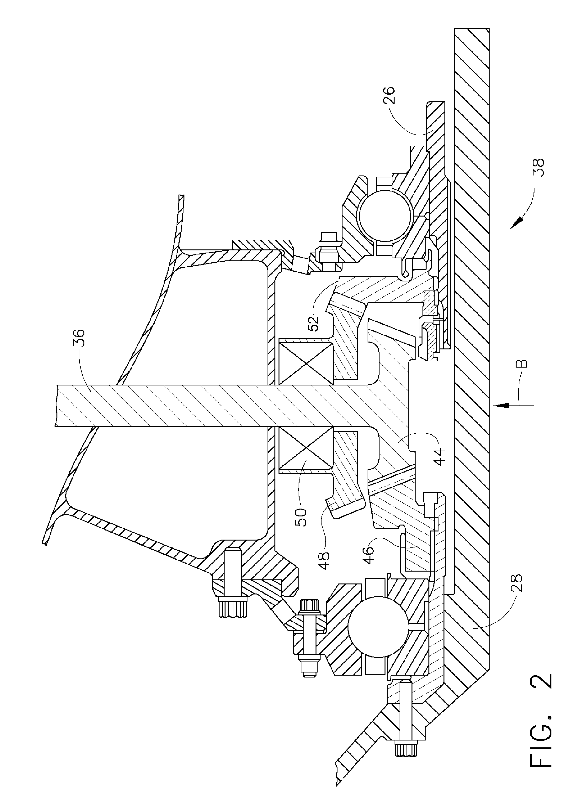
[0011] Referring to the drawings wherein identical reference numerals denote the same elements throughout the various views, FIG. 1 illustrates a representative gas turbine engine, generally designated 10. The engine 10 has a longitudinal center line or axis A and an outer stationary annular casing 12 disposed concentrically about and coaxially along the axis A. The engine 10 has a front fan 14, rear fan 15, booster 16, compressor 18, combustor 20, high pressure turbine 22, and counter-rotating low pressure turbine 24 arranged in serial flow relationship. In operation, pressurized air from the compressor 18 is mixed with fuel in the combustor 20 and ignited, thereby generating combustion gases. Some work is extracted from these gases by the high pressure turbine 22 which drives the compressor 18 via a high pressure drive shaft or “HP” shaft 26. The combustion gases then flow into a low pressure turbine 24, which drives the front fan 14, rear fan 15, and booster 16 via first and seco...


PUM


Abstract

A PTO apparatus for a gas turbine engine having first and second drive shafts includes a first ring gear for being coupled to the first drive shaft and a first bevel gear engaged with the first drive gear and coupled to a PTO shaft. A second ring gear is provided for being coupled to the second drive shaft. A second bevel gear is engaged with the second drive gear and coupled to the PTO shaft through a one-way clutch. A method of operating a gas turbine engine includes operatively coupling a PTO shaft to first and second drive shafts and providing a starting torque to the first and second drive shafts through the PTO shaft. After the engine is started, power is transferred from the first drive shaft to the PTO shaft; and the second shaft is decoupled from the PTO shaft.

Description

BACKGROUND OF THE INVENTION [0001] The present invention relates generally to gas turbines, and more particularly to a power take off drive assembly for a gas turbine. [0002] A gas turbine engine includes a compressor that provides pressurized air to a combustor wherein the air is mixed with fuel and ignited for generating hot combustion gases. These gases flow downstream to one or more turbines that extract energy therefrom to power the compressor and provide useful work such as powering an aircraft in flight. In a turbofan engine, which typically includes a fan placed at the front of the core engine, a high pressure turbine powers the compressor of the core engine. A low pressure turbine is disposed downstream from the high pressure turbine for powering the fan. [0003] In addition to providing thrust for flight, a gas turbine engine must operate additional power-absorbing accessories such as electrical generators, fuel pumps, hydraulic pumps, and the like. Accordingly, a power tak...

Claims


Application Information

Patent Timeline
Patent Type & Authority Applications(United States)
IPC IPC(8): F02C7/32
CPCF02C7/36F05D2260/85F05D2260/4031F02K3/04
Inventor HENRY, JOHN L.PATT, RAYMOND F.
Owner GENERAL ELECTRIC CO
Why Eureka
Try Eureka