
Portable electromagnetic induction heating device

a heating device and electromagnetic technology, applied in the direction of induction current sources, electric/magnetic/electromagnetic heating, manufacturing tools, etc., can solve the problems of generating further noise, heating metal sheets by using conventional coils, and taking time to cure until the adhesive solidifies, so as to improve the efficiency of generating eddy current and reliable heating

Inactive Publication Date: 2007-02-01
TOKYO DENKI UNIVERSITY
View PDF7 Cites 36 Cited by
  • Summary
  • Abstract
  • Description
  • Claims
  • Application Information

AI Technical Summary

Benefits of technology

[0011] An object of the present invention is to provide a portable electromagnetic induction heating device with small size and light weight.

Problems solved by technology

More specifically, when the interior materials are to be assembled by nails or the like, heads of the nails protrude from surfaces of the interior materials, so that the heads have to be concealed by ornaments or the like and further noise is generated during construction.
However, it takes time to cure until the adhesive solidifies.
When two members are to be bonded by the adhesive, heating the metal sheet by using the conventional coil is limited to donut-shaped heating or heating dependent on a donut-shaped induced electromotive force and a shape of the metal sheet.
Therefore, limit has been imposed on the heating of target regions of the metal sheets of various shapes.
For example, in heating a rectangular tape, only both ends of a tape portion facing the coil center portion are heated, whereby an end-burnt phenomenon is caused and there is in a state of being not usable in practice.
However, these are insufficient as the burnt-end countermeasures, and involve risks of fire.
For bonding of, for example, tiles that require wide-region bonding, there is no corresponding model among conventional devices, so that since these devices aim at only regions capable of being heated by the conventional coils, the heating of the center portion and corner portions becomes insufficient.
In the electromagnetic induction devices developed thus far, the current amount has been limited in terms of electrical power, heating efficiency is low, and control of the bonding region is limited.
However, uniform heating of a large area, which cannot be performed by the conventional techniques, is prevented by such design that ends of the core are increased.
Also, regarding control of the heating time, if the bonding portion is an ignitable member, over heating is extremely dangerous, so that detecting the heating temperature and controlling the supplied power are essential.
The conventional techniques lack consideration for performing such strict heating control.

Method used


Image

  • Portable electromagnetic induction heating device
  • Portable electromagnetic induction heating device
  • Portable electromagnetic induction heating device

Examples


Embodiment Construction

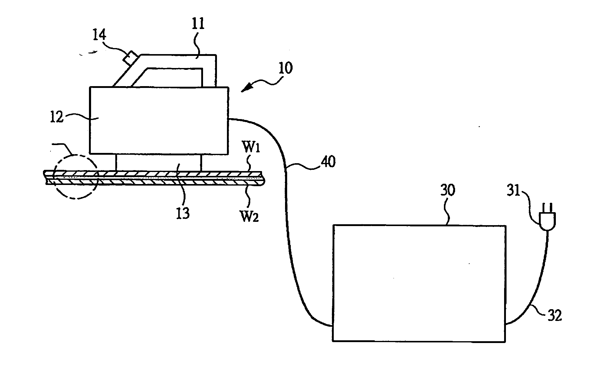
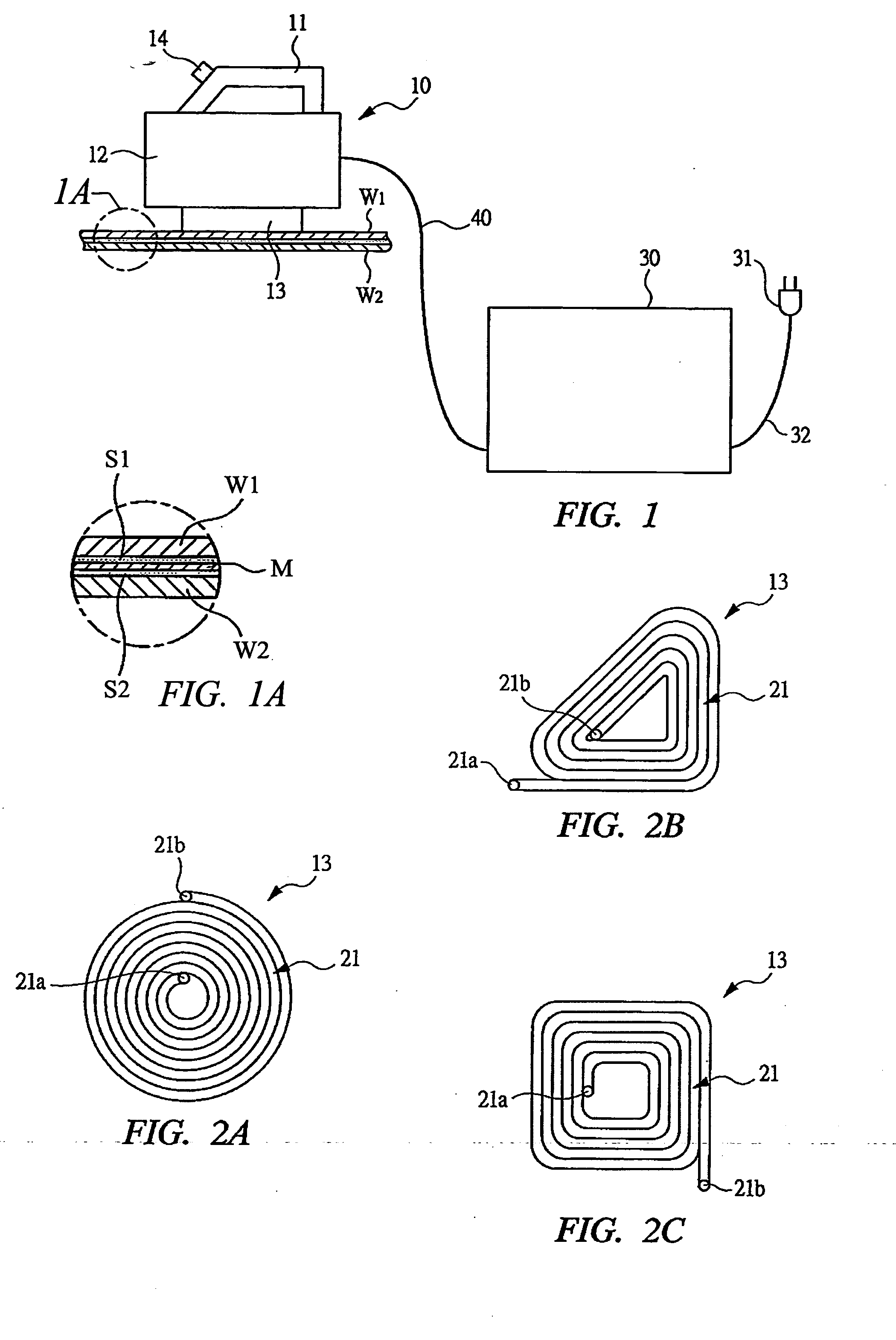
[0043] In FIGS. 1 and 1A, a state in which two members W1 and W2 are bonded by thermoplastic adhesive is shown, and a conductive sheet M comprising metal foil to whose both surfaces adhesive S1 and S2 are applied is disposed between the two members W1 and W2. The sheet M is made of aluminum or steel. The sheet M comprising the metal foil which is a conductor, i.e., a conductive member is made to generate heat by an electromagnetic induction effect, and the adhesive S1 and S2 are heated by the heat to melt the adhesive in a short time in seconds, whereby the members W1 and W2 can be mutually bonded. If the metal foil is similarly made to generate heat by a portable electromagnetic induction heating device to melt the adhesive, the members W1 and W2 bonded by the adhesive can be peeled off from each other. By using the portable electromagnetic induction heating device shown in FIG. 1 in the above described manner, for example, when the respective members W1 and W2 are wood or plaster ...


PUM

PropertyMeasurementUnit
frequencyaaaaaaaaaa
inductanceaaaaaaaaaa
magnetic forceaaaaaaaaaa

Abstract

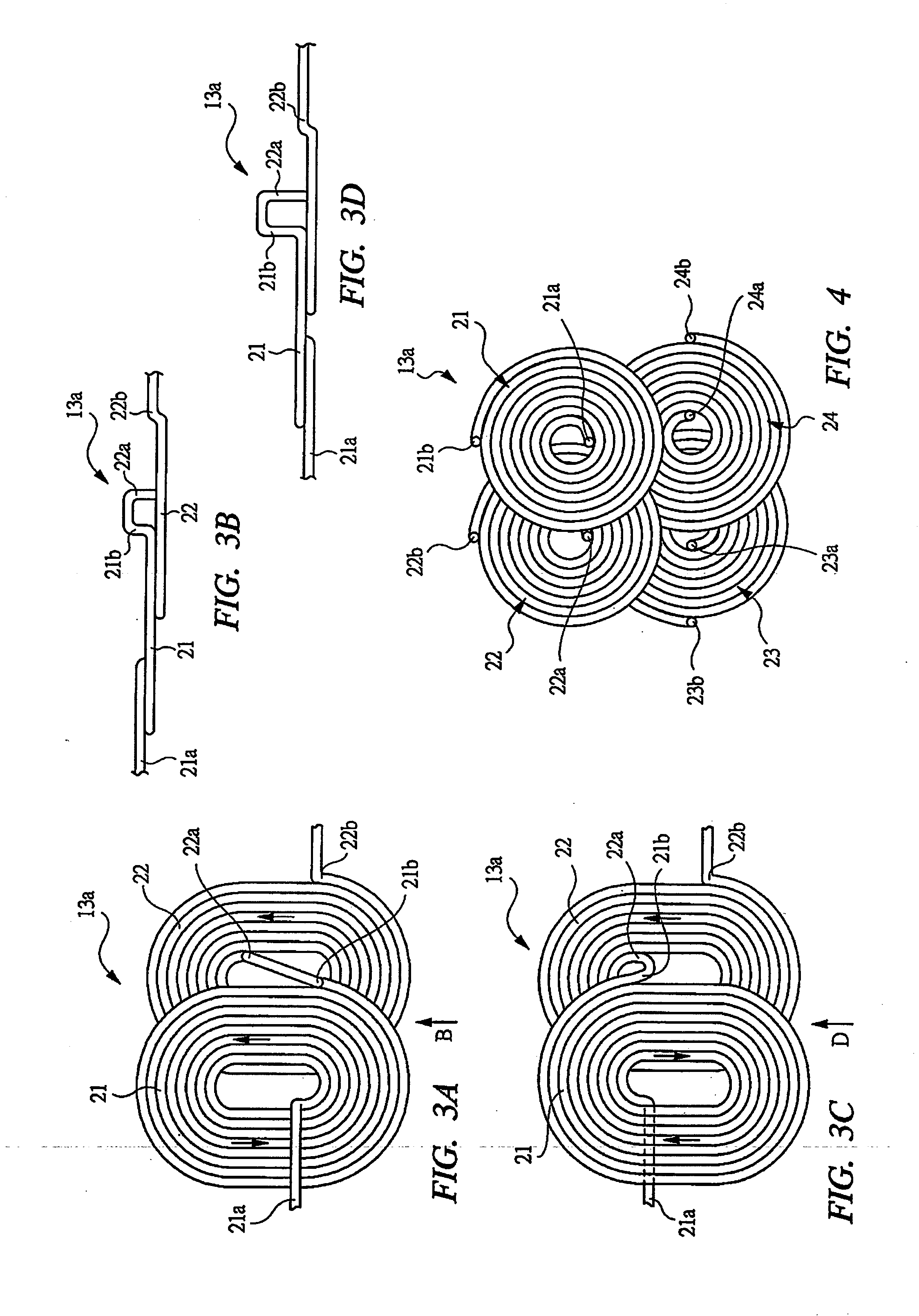
This portable electromagnetic induction heating device is used to carry an induction current in a conductor, make the conductor generate heat by Joule's heat, and heat adhesive by the heat generating conductor. A heating induction coil (13a) is formed by a plurality of coil bodies (21-24 and 51-54), the respective coil bodies can change mutually center-to-center distances. Simultaneously, by changing any one of polarities thereof, a polarity and a position of a magnetic force line generated by the conductor are changed, whereby a heating state of the adhesive can be changed depending on a region of the adhesive.

Description

CROSS REFERENCE TO RELATED APPLICATIONS [0001] This application is entitled to the benefit of and incorporates by reference essential subject matter disclosed in International Patent Application No. PCT / JP2003 / 015972 filed on Dec. 12, 2003, Japanese Patent Application No. 2003-154582 filed May 30,2003 and Japanese Patent Application No. 2003-310457 filed Sep. 2, 2003. TECHNICAL FIELD [0002] The present invention relates to a portable electromagnetic induction heating device for making a conductor generate heat by electromagnetic induction heating and for heating adhesive. BACKGROUND OF THE INVENTION [0003] In order to bond a conductive member such as metal and a nonconductive member such as wood by the adhesive, a technique for making the conductive member generate heat by an induction coil, i.e., a heating coil and for heating the adhesive is disclosed in Japanese Patent Laid-Open Publication No. 8-73818. Also, in order to bond the nonconductive members to each other, a technique f...

Claims


Application Information

Patent Timeline
Patent Type & Authority Applications(United States)
IPC IPC(8): H05B6/10E04F21/18C09J5/06C09J201/00E04F21/20H05B6/04H05B6/06H05B6/14H05B6/36H05B6/44
CPCH05B6/36H05B6/105
Inventor OBATA, SHUJITANIMITSU, MASATAKATOMITA, HIDEOYOSHIMURA, SHINZOSUZUKI, KUNIHIKO
Owner TOKYO DENKI UNIVERSITY
Learn More