Dual conversion gain gate and capacitor combination

a gain gate and capacitor technology, applied in the field of digital image sensors, can solve the problems of reducing the dynamic range available for the pixel cell, reducing the efficiency of the pixel cell, so as to increase the efficient use of space

Active Publication Date: 2007-02-01
MICRON TECH INC
View PDF16 Cites 74 Cited by
  • Summary
  • Abstract
  • Description
  • Claims
  • Application Information

AI Technical Summary

Problems solved by technology

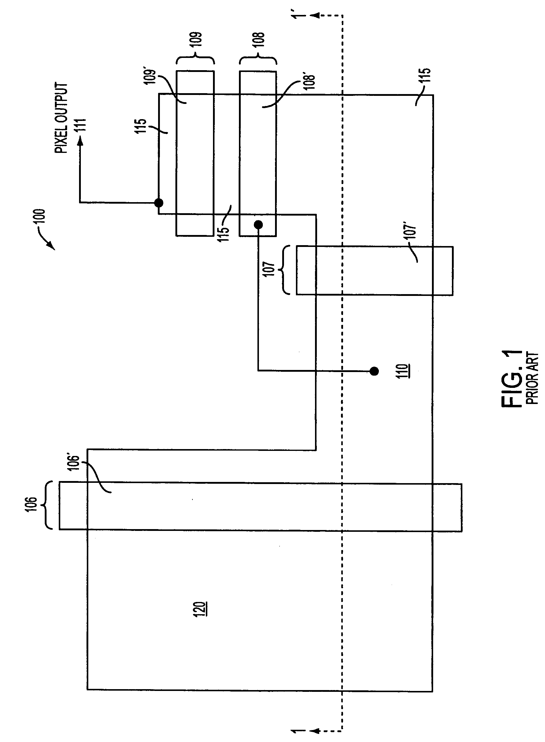
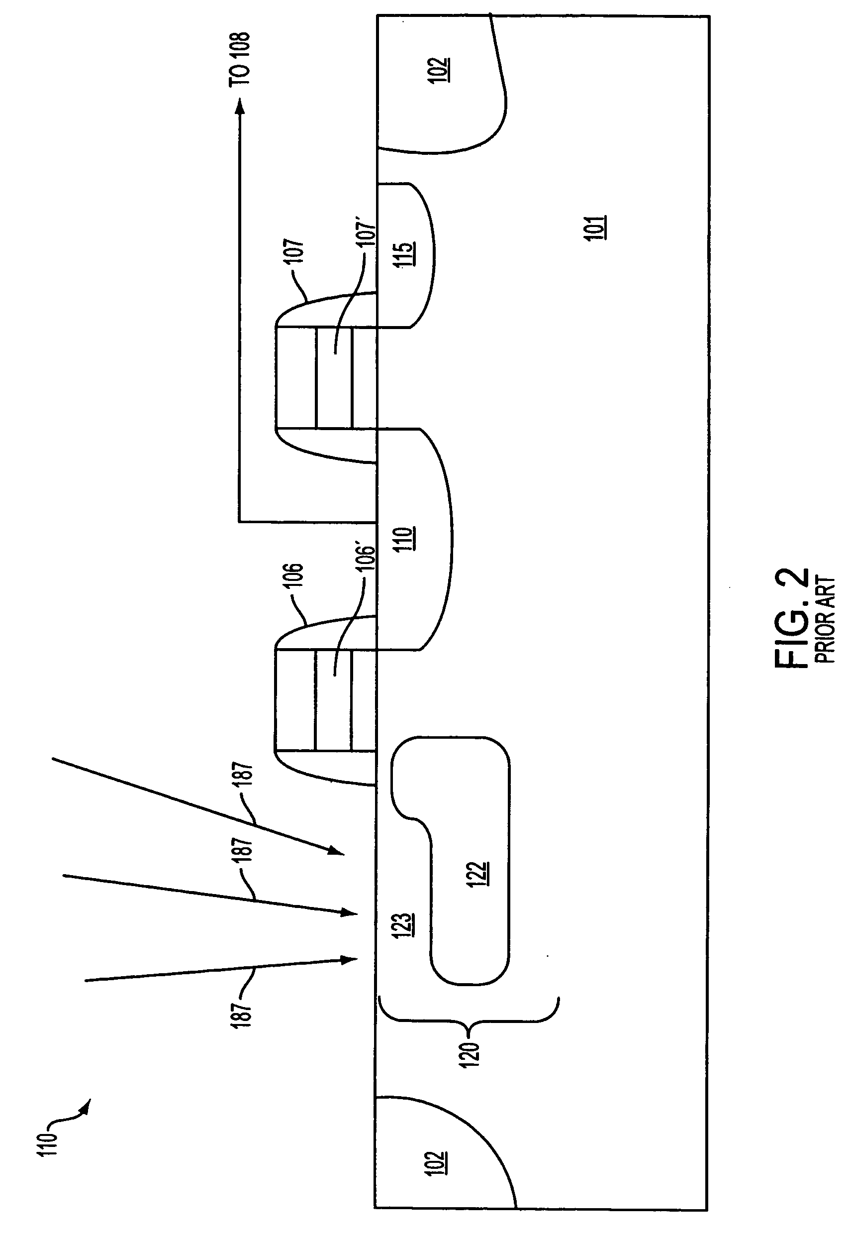
In addition, conventional storage nodes, such as floating diffusion region 110, have a limited amount of charge storage capacity.
Once this capacity is reached, a pixel cell becomes less efficient.
Specifically, the full dynamic range available for the pixel cell cannot be utilized.
Once the charge storage capacity is exceeded, an undesirable phenomenon, known as “blooming” occurs, whereby the “over-capacity” charges escape to undesirable parts of the pixel cell 100 or to adjacent pixel cells.
The problem with this solution, however, is that the additional capacitor takes up space in the cell that could otherwise be used to increase the size of the cell's photosensor, thereby decreasing the potential fill factor for the pixel cells and overall array.

Method used


Image

  • Dual conversion gain gate and capacitor combination
  • Dual conversion gain gate and capacitor combination
  • Dual conversion gain gate and capacitor combination

Examples


Embodiment Construction

[0022] In the following detailed description, reference is made to the accompanying drawings, which form a part hereof and show by way of illustration specific embodiments in which the invention may be practiced. These embodiments are described in sufficient detail to enable those skilled in the art to practice the invention, and it is to be understood that other embodiments may be utilized, and that structural, logical, and electrical changes may be made without departing from the spirit and scope of the present invention. The progression of processing steps described is exemplary of embodiments of the invention; however, the sequence of steps is not limited to that set forth herein and may be changed as is known in the art, with the exception of steps necessarily occurring in a certain order.

[0023] The terms “wafer” and “substrate,” as used herein, are to be understood as including silicon, epitaxial, silicon-on-insulator (SOI) or silicon-on-sapphire (SOS) technology, doped and u...


PUM


Abstract

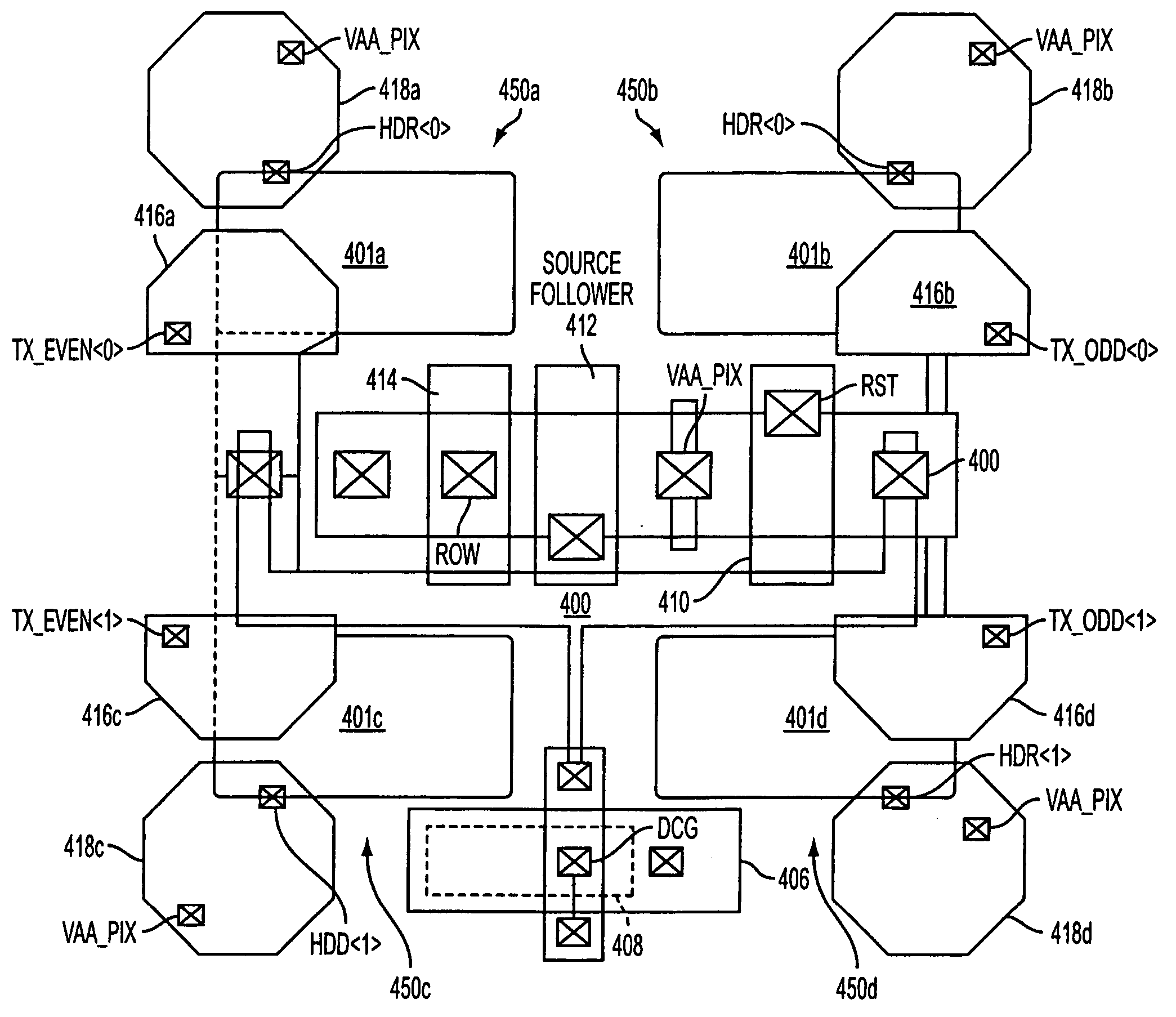
A pixel cell array architecture having a dual conversion gain. A dual conversion gain element is coupled between a floating diffusion region and a respective storage capacitor. The dual conversion gain element having a control gate switches in the capacitance of the capacitor to change the conversion gain of the floating diffusion region from a first conversion gain to a second conversion gain. In order to increase the efficient use of space, the dual conversion gain element gate also functions as the bottom plate of the capacitor. In one particular embodiment of the invention, a high dynamic range transistor is used in conjunction with a pixel cell having a capacitor-DCG gate combination; in another embodiment, adjacent pixels share pixel components, including the capacitor-DCG combination.

Description

FIELD OF THE INVENTION [0001] The present invention relates generally to digital image sensors and in particular to dual conversion gain imagers. BACKGROUND OF THE INVENTION [0002] Imaging devices, including charge coupled devices (CCD) and complementary metal oxide semiconductor (CMOS) imagers, are commonly used in photo-imaging applications. [0003] Typically, a digital imager array includes a focal plane array of pixel cells, each one of the cells including a photosensor, e.g., a photogate, photoconductor, or a photodiode. In a CMOS imager a readout circuit is connected to each pixel cell which typically includes a source follower output transistor. The photosensor converts photons to electrons which are typically transferred to a storage node, e.g., a floating diffusion region connected to the gate of the source follower output transistor. A charge transfer device (e.g., transistor) can be included for transferring charge from the photosensor to the floating diffusion region. In ...

Claims


Application Information

Patent Timeline
Patent Type & Authority Applications(United States)
IPC IPC(8): H01L31/113
CPCH01L27/14603H01L27/14609H01L27/14689H01L27/14641H04N5/374H04N5/37452H04N5/37457H04N5/3559H04N25/59H04N25/778H04N25/771H04N25/76H04N25/77
Inventor MCKEE, JEFFREY A.
Owner MICRON TECH INC
Why Eureka
Try Eureka