Micro-manipulator

a micro-manipulator and hand-held technology, applied in the field of micro-manipulators, can solve the problems of multiple attempts, troublesome conventional micro-manipulators, damage, etc., and achieve the effect of accurately and quickly positioning the micro-material and facilitating the gripping of the fingers

Active Publication Date: 2007-02-01
TOKYO INST OF TECH +1
View PDF1 Cites 8 Cited by
  • Summary
  • Abstract
  • Description
  • Claims
  • Application Information

AI Technical Summary

Benefits of technology

[0017] According to one aspect of the invention, gripping means are moved in the X and Y directions by the first moving means, and in the Z direction by the second moving means. Furthermore, the first moving means change the position direction of the gripping means by swinging the gripping fingers centering on the leading ends of the gripping fingers of the gripping means, so it is possible to easily position the gripping fingers with regard to the micro-material in the microscope visual field, and accurately and quickly position the micro-material.
[0018] The second moving means is supported by the first moving means, and the gripping means is supported by the first moving means so there is no load of the gripping means applied to the second moving means. Therefore, little driving force is needed to move in a Z direction that is opposite to the force of gravity, and therefore consumes a low amount of power.
[0019] Furthermore, a micro-manipulator comprising first moving means that includes a configuration for moving the gripping means in the X and Y directions and for changing the position of the gripping means to swing the gripping fingers centering on the leading ends of the gripping fingers of the gripping means may provide a more compact micro-manipulator.

Problems solved by technology

However, because the leading ends of the gripping fingers must be manually positioned relative to the micro-material to be gripped, conventional micro-manipulators are troublesome in that they may require trial and error to get the leading ends of the gripping fingers to grip the micro-material.
Furthermore, if the object to be gripped is a cell, it may be damaged after multiple attempts.
However, unlike the movement in the X and Y directions, the movement of the leading ends of the gripping fingers in the Z direction opposes the direction of gravity and therefore such a feature is accompanied by an increase in the amount of energy consumed.

Method used


Image

  • Micro-manipulator
  • Micro-manipulator
  • Micro-manipulator

Examples


Embodiment Construction

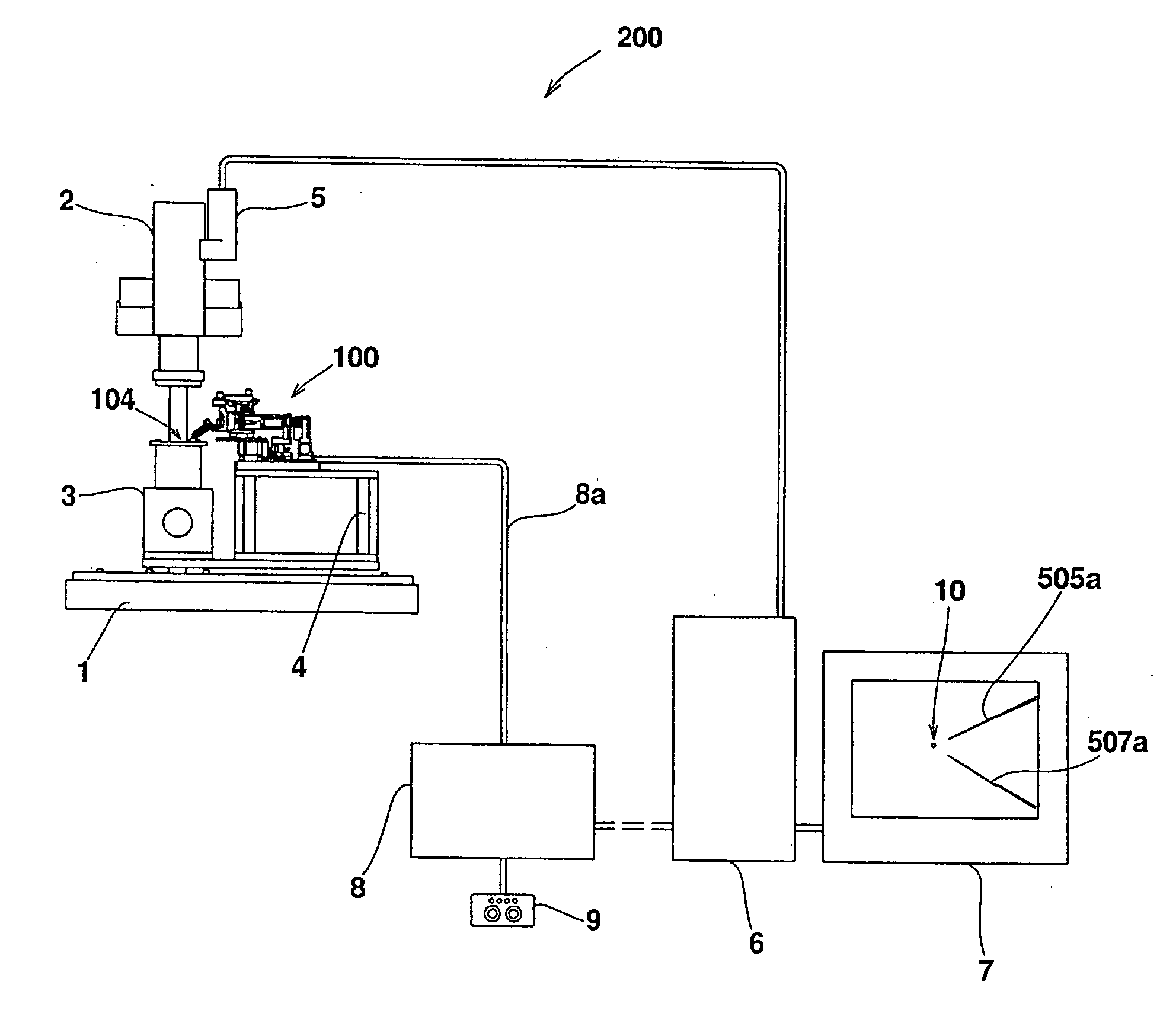
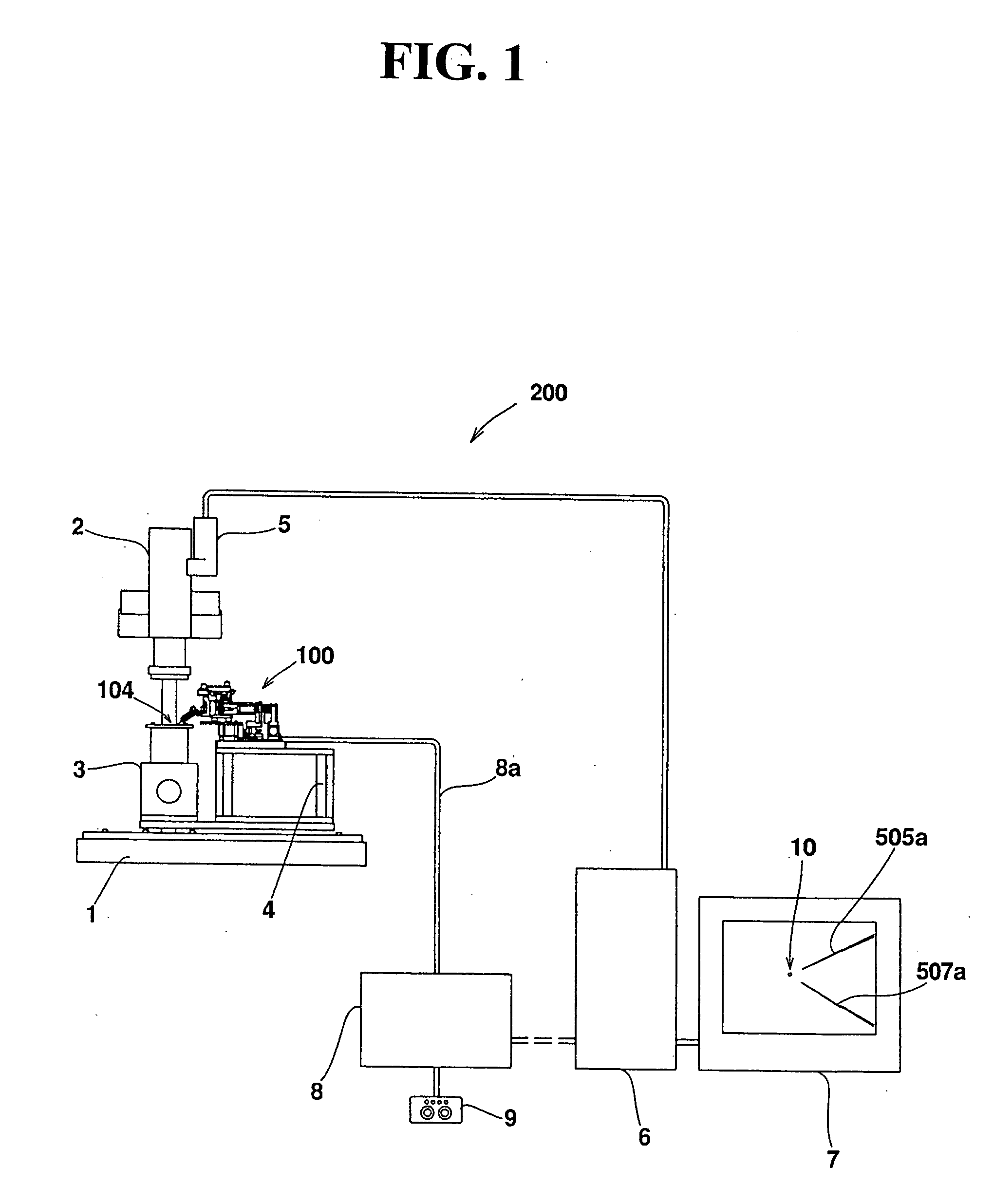
[0032] The following will explain the micro-manipulator according to the present invention with reference to the drawings provided, as it is applied to a micro-material handling system for positioning micro-material such as cells or micro-components.

[0033] As shown in FIG. 1, one embodiment of a micro-material handling system 200 includes a micro-material handling device or micro-manipulator 100 that is mounted on a surface plate 1 via a mount 4, and includes a stage 3 fastened to the surface plate 1 for placing micro-material to be handled by the micro-manipulator 100. The micro-material handling system 200 is also equipped with a microscope 2 whose column support is fastened to the surface plate 1 and is mounted with a charge coupled device (CCD) camera, a personal computer (hereinafter referred to as a PC), and a control box embedded with a programmable logic controller (PLC) for controlling the micro-manipulator 100 as a slave computer of PC 6.

[0034] The PC 6 is connected with...


PUM


Abstract

A compact micro-manipulator with low energy consumption accurately and quickly positions a micro-material in a visual field of a microscope. A micro-manipulator operable to grip micro-material by bringing leading ends of the gripping fingers in close proximity includes an XY drive unit that drives a handling unit in X and Y directions, a drive unit that changes a positional direction of the handling unit in order to swing the gripping fingers around leading ends of the gripping fingers, and a Z drive unit that drives the handling unit in the Z direction.

Description

BACKGROUND OF THE INVENTION AND RELATED ART STATEMENT [0001] The present invention relates to micro-manipulators, and particularly to micro-manipulators that bring leading ends of gripping fingers into close proximity to handle micro-materials. [0002] Micro-manipulators are used to assemble micro-parts or to handle cells. Generally, a micro-manipulator has a mechanism for moving gripping fingers to handle (grip) micro-objects (Japanese Patent Publication No. 8-168979, for example). Because the material to be gripped is minute, an operator normally watches the images under a microscope, with the naked eye. Alternatively, images output by a monitor, such as a display via a camera mounted on the microscope, are used to allow a user to operate the micro-manipulator (Japanese Patent Publication No. 4-303810, for example). [0003] In addition, conventional micro-manipulators usually comprise a micro-material state (setting stage), on which the micro-material is disposed in a direction so t...

Claims


Application Information

Patent Timeline
Patent Type & Authority Applications(United States)
IPC IPC(8): B65H5/02
CPCB25J7/00Y10T74/20305Y10S414/13B25J9/1065
Inventor HORIE, MIKIOKAMIYA, DAIKIMOCHIZUKI, NAOTOYODA, YOSHIMICHIKOUNO, MASAHIRO
Owner TOKYO INST OF TECH
Why Eureka
Try Eureka