Motor
Inactive Publication Date: 2007-02-01
NIDEC CORP
13 Cites 29 Cited by
AI-Extracted Technical Summary
Problems solved by technology
However, with such structure as mentioned above, there may be situations in which magnetic force strong enough to retain the rotor section are not generated.
That is, when the motor is installed on an electric equipment, the rotor cannot be attached to the electric equipment while the rotor section is facing vertically downward.
Further, when an external pressure is applied to the motor in the axial direction, the rotor section of the motor may be forced to move in the axial direction.
When such pressure is applied to the motor, hitting noise, which is generated by the end of the shaft and t...
Benefits of technology
[0007] An aforementioned configuration where the magnet holder is affixed to the bearing retaining section allows a strong joint strength therebetween. Also, since a surface of the magnet holder and the bearing retaining section are tightly affixed to one another, an oil leakage from a section bordering between the magnet holder and the bearing retaining section will be prevented.
[0008] With the aforementioned configuration, where the oil leakage is prevented, a thickness of the bearing retaining sect...
Abstract
A thrust plate for supporting a bottom end of a shaft in an axial direction is provided on a top surface of a bottom section of a bearing housing. An attracting magnet for attracting the shaft, which is made of a magnetic material, in the axial direction is provided below the thrust plate. A substantially cup shaped magnet holder is provided surrounding a periphery of the attracting magnet. The magnet holder retains the attracting magnet by a bottom section and a radial periphery surface of the attracting magnet. The magnet holder is integrally formed, by an insert molding, with the bottom section of the bearing housing.
Application Domain
Pump componentsShafts +10
Technology Topic
Magnet
Image
Examples
- Experimental program(1)
Example
First Embodiment
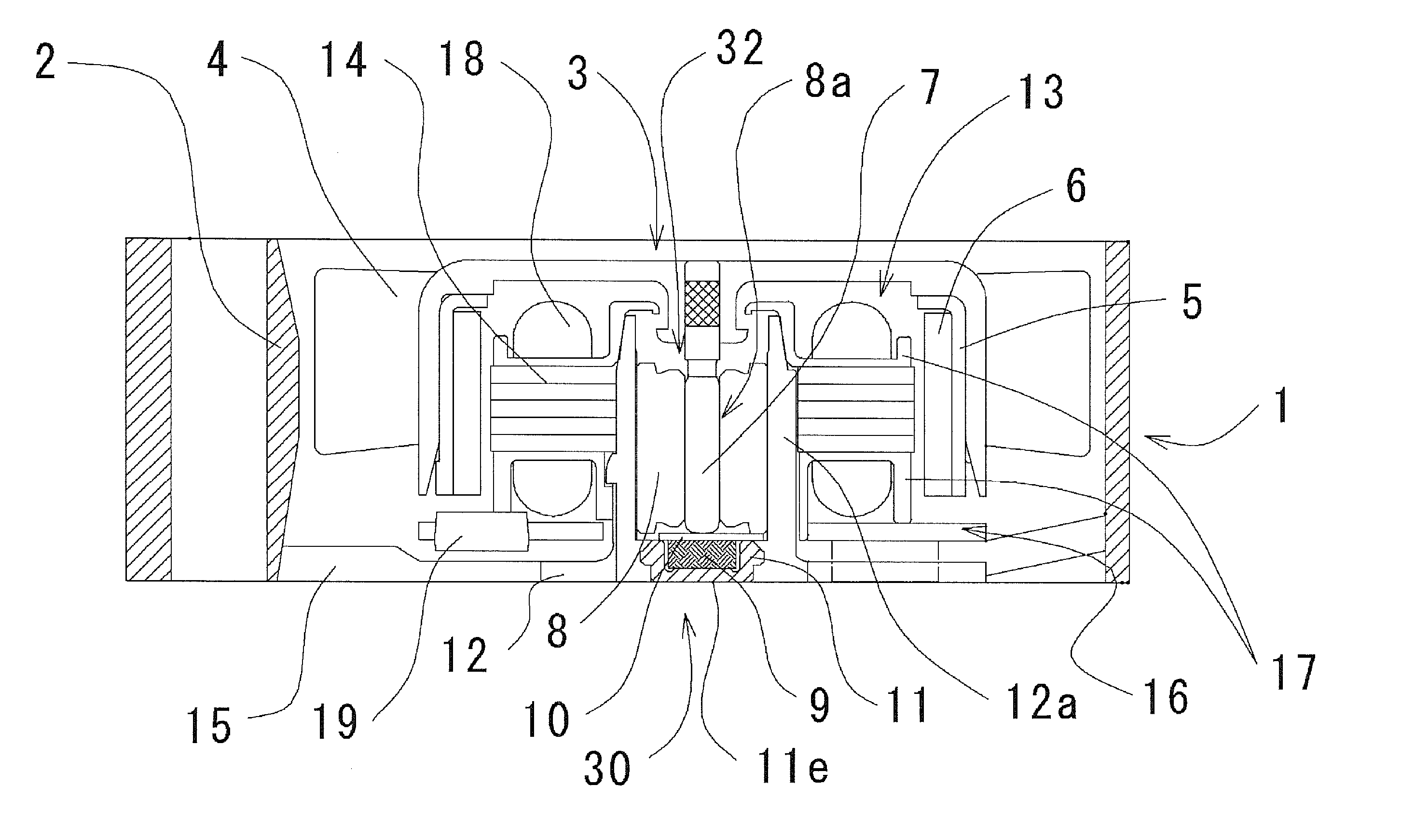
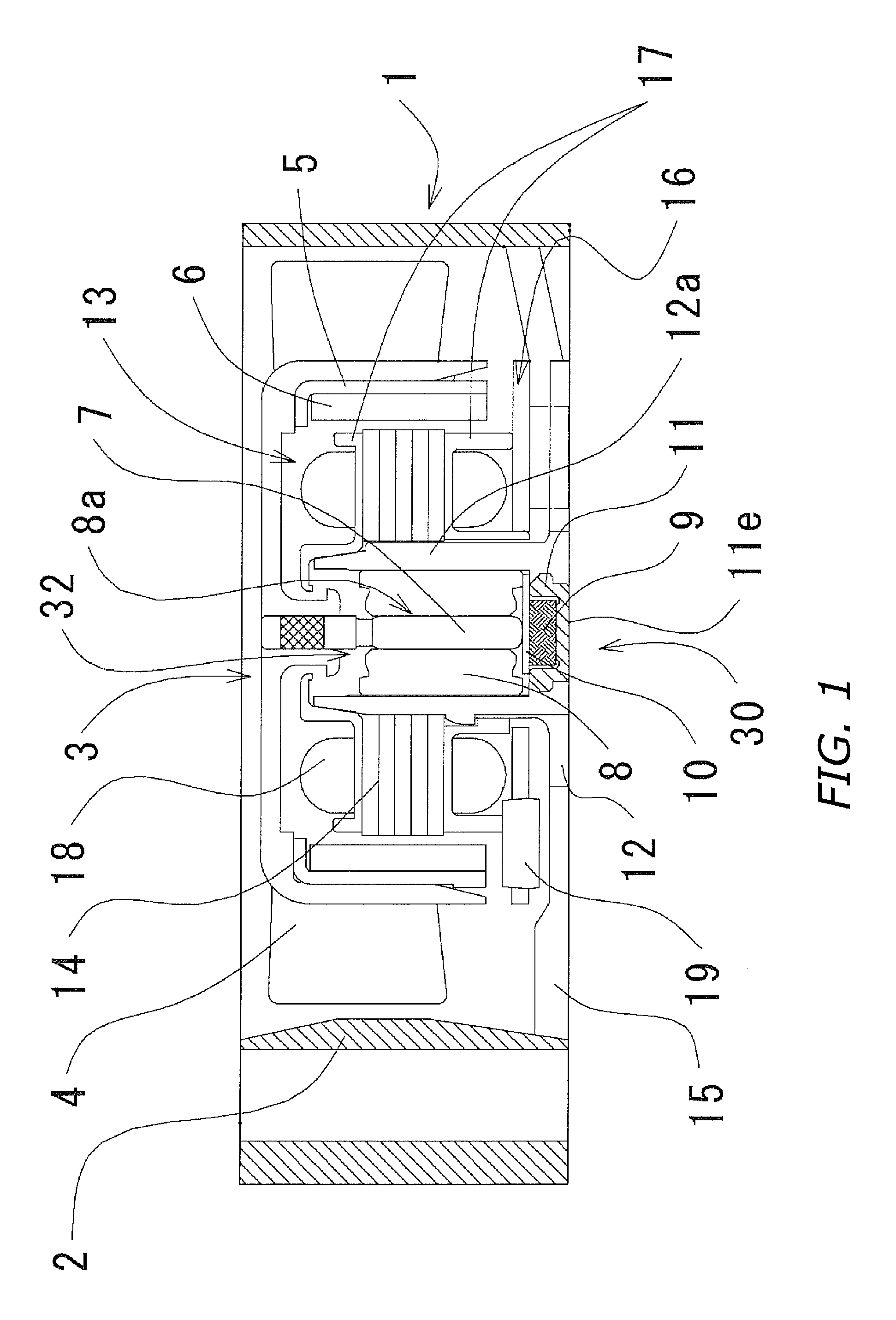
[0021]FIG. 1 is a diagram illustrating a cross section of an embodiment of a motor of the present invention. Hereinafter, the motor used for a fan will be described.
[0022] A fan 1 has a structure in which a rotor section 3, which drives rotationally once an external electric current is applied thereto, has attached thereto an impeller 4 having a plurality of blades. The rotor section 3 includes a shaft 7. The shaft 7 and the impeller 4 are integrally provided such that one end of the shaft 7 is affixed to a center section of the impeller 4. The impeller 4 is formed by a resin injection mold. The one end of the shaft 7 is inserted in a die forming the impeller 4, and the one end will be covered by resin forming the impeller 4 thereby affixing the shaft 7 to the impeller 4.
[0023] Further, the fan 1 includes therein a bearing unit 30. The bearing unit 30 includes therein the shaft 7, a bearing retaining section, a sleeve 8, and an attracting magnet which will be described later.
[0024] At a center section of a frame 12, a substantially cup shaped bearing housing 12a, which is the bearing retaining section, is provided. A bearing housing 12a and the frame 12 are formed integrally and seamlessly with one another by using an injection molding.
[0025] The sleeve 8 is supported by being press fit into the bearing housing 12a. Further, the sleeve 8 includes therein an through hole 8a so as to allow the shaft 7 to rotate therein. The shaft 7 is inserted through the through hole. The sleeve 8 is comprised of a porous sintered metallic material and is formed by a powder metallurgy method. The sleeve 8 is impregnated with oil as a lubricant for the shaft 7 to rotate therein. Therefore, the shaft 7, or the rotation thereof, is supported by the sleeve 8 through the lubricant.
[0026] A radial bearing mechanism 32 for supporting, while maintaining the aforementioned lubricant as a working fluid, the shaft 7 when the rotor section 3 rotates is formed between an exterior surface of the shaft 7 and an interior surface of the sleeve 8. The radial bearing mechanism 32 is comprised of, for example, a sliding bearing, a fluid dynamic bearing or the like.
[0027] A stator section 13 is supported by an exterior section of the bearing housing 12a. The stator section 13 is comprised of a stator core, a coil, an insulator 17 for insulating the stator core from the coil, and a circuit board 16. The stator core is surrounded by the insulator 17, which is composed of an electrical insulating material so as to electrically insulate an upper end, a bottom end and a plurality of teeth sections. The coil winds each teeth section along with the insulator 17. A circuit board 16 having mounted thereon a driver circuit is provided at a bottom part of the stator section 13. The circuit board 16 controls a rotary drive of the rotor section 3. The circuit board 16 comprises a printed board having mounted thereon electronic components. A design of a circuit to be mounted on the printed board is printed on a surface of the circuit board 16, to which the coil and electronic components are electrically connected so as to form a drive control circuit. The circuit board 16 is affixed to a bottom end of the insulator 17. A magnetic field is generated to the stator core when externally supplied electricity is applied to the coil through the electronic components including IC and a hall element 19.
[0028] On an inner circumference of the impeller 4, a multipoled rotor magnet 6 is provided. Also, a rotor yoke 5 for retaining from a circumference of the rotor magnet 6 the rotor magnet 6 is provided so as to reduce an amount of magnetic flux which may be leaked to the fan 1. When the shaft 7, which is integrally formed with the impeller 4, is inserted into the sleeve 8, the rotor magnet 6 and the stator core will be positioned such that the rotor magnet 6 and the stator core face one another radially. Rotary torque, which is generated in the rotor section 3 due to a mutual effect between a magnetic field generated by the stator core and a magnetic field generated by the rotor magnet 6, rotates the rotor section 3 around the shaft 7. Stability of the rotation of the rotor section 3 is controlled by a drive IC switching a voltage output after the hall element 19 detects a change in the flux generated by the rotating rotor magnet 5. The impeller 4 retained on an exterior circumference of the rotor section 3 rotates due to the rotary drive of the rotor section 3, thereby generating an airflow.
[0029] The frame 12 is positioned facing the circuit board 16 in an axial direction, and is formed to be a disc shape having an outer diameter which is substantially equivalent to, but not limited to, an outer diameter of the circuit board 16. An air channel section 2 for forming a pathway for the airflow generated by the impeller 4 is provided radially outward of the frame 12. A plurality of ribs 15 which stretch outward in a radial direction are provided on an exterior of the frame 12. An end of each rib 15 in a radial direction is connectedly affixed to the air channel section 2. The rotor section 3 including the impeller 4 is contained in an inner space of the air channel section 2.
[0030] A thrust plate 10 for supporting the shaft 7 at a bottom end of the shaft 7 in the axial direction is provided at an upward facing bottom end of the bearing housing 12a. Since the bottom end of the shaft 7 makes contact with the thrust plate 10, the contacting surfaces slide against one another. Therefore, the thrust plate 10 is to be composed of a material durable against friction, which occurs when the thrust plate 10 and the shaft 7 slide against one another.
[0031] An attracting magnet 9 for magnetically attracting the shaft 7, which is composed in part of a magnetic material, is provided at a bottom end of the thrust plate 10. A substantially cup shaped magnet holder 11 is provided surrounding a periphery of the attracting magnet 9. The magnetic holder 11 retains the attracting magnet 9 by retaining a bottom end and the periphery in a radial direction of the attracting magnet 9. The magnet holder 11 and the attracting magnet 9 are affixed to one another by a magnetic force of the attracting magnet 9. Note that when the magnet holder 11 and the attracting magnet 9 need to be affixed to one another more firmly than by the magnetic force of the attracting magnet 9, an adhesive may be used therebetween. Since the magnet holder 11 is a magnetic substance, the magnet holder 11 significantly reduces an amount of the magnetic flux which may be leaked out of the attracting magnet 9 to the fan 1. Further, due to a magnetic circuit generated by the magnet holder 11 and the attracting magnet 9, a magnetic flux density of the attracting magnet 9 will be increased thereby increasing the attraction force of the attracting magnet 9 attracting the shaft 7. Therefore, the rotor section 3 will become stabilized in the axial direction. Consequently, compared with a conventional method in which an axial magnetic center of a section equivalent to the rotor magnet 6 is modified in accordance with an axial magnetic center of a section equivalent to the stator section 13, noise generated by the magnetic field will be reduced.
[0032] The magnet holder 11 is, as illustrated in FIG. 2, formed at a bottom surface of the bearing housing 12a by an insert molding method, which will be described below, such that the magnet holder 11 and the bearing housing 12a are integrated with one another and are facing a same direction. That is, an interior of the substantially cup shaped magnet holder 11 and the interior of the bearing housing 12a are integrally formed in a same manner that the attracting magnet 9 is affixed the interior of the bearing unit 30.
[0033] Melted resin is applied on a section of a surface, of the magnet holder 11, contacting with the bearing housing 12a and with the frame 12. The melted resin is cooled on the surfaces so as to connect surfaces between the magnet holder 11 and the bearing housing 12a, and between the magnet holder 11 and the frame 12. Therefore, the magnet holder 11 is tightly connected to the bearing housing 12a and to the frame 12 such that no space is generated between the magnet holder 11 and the bearing housing 12a, and between the magnet holder 11 and the frame 12, thereby preventing an oil leakage to an exterior of the fan 1 from an area near a bottom end, of the frame 12, connecting to the magnet holder 11.
[0034] Further, an exterior of a substantially cup shaped base section 11e is exposed to the exterior of the frame 12. Therefore, it becomes possible to reduce a thickness of the bearing unit. Note that the base section 11e of the magnet holder 11 may be, instead of being exposed to the exterior of the frame 12, covered in resin in order to strengthen the connection between the magnet holder 11 and the bearing housing 12a, and the magnet holder 11 and the frame 12.
[0035] Further, the magnet holder 11 of the present embodiment is composed of a magnetic sintered metal. That is, the magnet holder 11 is a porous sintered metal formed by the metal ceramic process. When an inner diameter of the magnet holder 11 is greater than φ3 mm, the magnet holder can easily be formed by pressing a magnetic metal plate. Therefore, the magnet holder 11 can be formed by a method other than the metal ceramic process depending on a size of the magnet holder 11. Since the base section 11e of the magnet holder 11 is exposed to the exterior of the frame 12, it is important that the oil retained in the bearing mechanism is prevented from being leaked to the fan 1 through the interior of the magnet holder 11 and the base section 11e. In order to prevent the oil leakage, there is a method to reduce a number and a size of pores formed in the interior of the magnet holder 11. For example, the magnet holder 11 is to be composed mainly of iron wherein less than 10% of a total weigh thereof is composed of an iron-copper type material such that a weight density of the magnet holder 11 is 6.45 to 6.80 g/cm3. With such material, it is possible to reduce the number and the size of pores formed in the interior of the magnet holder 11, thereby preventing the oil leakage. However, using a material different from the aforementioned material to compose the magnet holder 11 may form pores having a different size. Therefore, a new standard for controlling the weight density needs to be applied in accordance with the new material.
[0036] Further, a steam treatment process can be applied to the magnet holder 11. The steam treatment process is a process in which the magnet holder 11 is heated for approximately 30 to 60 minutes by a superheated steam having a temperature between 500 to 600° C. so as to form an oxide film (e.g., Fe304) on a surface of the magnet holder 11, thereby improving durability of the surface of the magnet holder 11 against friction and corrosion. When the oxide film formed on the surface of the magnet holder 11 covers the pores, the oil leakage to the fan 1 will be prevented.
[0037] Further, a masking process can be applied on the surface of the magnet holder 11 so as to prevent the oil leakage to the fan 1 through the pores of the magnet holder 11. The masking process is a process in which a coating agent is applied on the surface of the magnet holder 11, or a process in which the surface of the magnet holder is ground until the surface is clear of the pores, thereby preventing the oil leakage to the fan 1 from the magnet holder 11. More particularly, the masking process can be: applied by grinding, using a cutting tool, the surface of the magnet holder 11; a shot blasting process in which metal powder or particle is sprayed on the magnet holder 11 so as to remove the pores from the surface thereof; or a coating process in which resin is coated on the surface of the magnet holder 11 so as to cover the pores on the surface thereof.
[0038] Further, the magnet holder 11 may be coated with oil repellent resin so as to cover the pores on, at least, the surface of the magnet holder 11 thereby covering majority of pores formed inside the magnet holder 11. By applying any one, or combination, of the processes mentioned above, the magnet holder 11 is, by an effect of the oil repellent resin, able to repel oil that is being leaked thereto. Note that the masking process or/and the process in which the magnet holder 11 is impregnated with the oil repellent resin is to be executed prior to when the magnet holder 11 is formed inside the frame 12.
[0039] Another means to prevent the oil from penetrating the pores formed inside the magnet holder 11 are as follows. Prior to when the magnet holder 11 is formed inside the frame 12, an entire circumference of an upper border between the magnet holder 11 and the frame 12, and an entire exposed area of the upper section of the magnet holder 11 are coated with the oil repellent resin. Since the entire circumference of the upper border between the magnet holder 11 and the frame 12, and the entire exposed area of the upper section of the magnet holder 11 are coated with the oil repellent resin, the oil repellent effect of the surface of the magnet holder 11 prevents a permeation of the leaked oil into the pores formed inside the magnet holder 11.
[0040]FIG. 2A is a diagram illustrating a cross section of the magnet holder 11. FIG. 2B is a diagram illustrating a perspective view of the magnet holder 11. As illustrated in FIGS. 2A and 2B, a toric convex section 11a, which protrudes outward radially, is provided on upper part of a circumference of the magnet holder 11. Further, on a circumference of the convex section 11a, 4 of concave sections 11b are provided, wherein each concave section 11b is equally positioned circumferentially from one another. Note that there may be more than or less than 4 concave sections 11b provided on the surface of the convex section 11a.
[0041] Since the convex section 11a and the concave section 11b are provided on the magnet holder 11, wherein the frame 12 and the magnet holder 11 are integrally formed by the insert molding, a retaining strength of the frame 12 retaining the magnet holder 11, and a rotary strength of the frame will be improved. Inside the injection molding, an injection pressure at which the melted resin is injected exceeds, at maximum, 100 kg/cm2. That is, inside the insertion molding, a pressure exceeding 1000 kg/cm2 is applied on the magnet holder 11, which is a material that is inserted. Although such high pressure is applied to the magnet holder 11 in the radial direction, due to the convex section 11a provided on the circumference of the magnet holder 11, a radial distortion, which may occur to the magnet holder 11, is kept to a minimum. Configurations of the convex section 11a and the concave section 11b are not restricted to as those illustrated in Figs. The configurations can be modified as long as they are able to: improve the retaining strength of the frame 12 retaining the magnet holder 11; and keep the distortion occurring to the magnet holder 11 due to the injection pressure to the minimum.
[0042]FIG. 3 is a diagram illustrating a perspective view of the thrust plate 10. FIG. 4 is a diagram illustrating, into details of, a pathway for airflow generated when the shaft 7 is inserted into the sleeve 8, wherein arrows indicate the airflow. As illustrated in FIG. 3, the thrust plate 10 is disc shaped having on its circumference at least one section that is notched.
[0043] As illustrated in FIG. 4, when inserting the shaft 7 into the through hole 8a of the sleeve 8, a nearly closed space (hereinafter, closed space) will be generated by a tip of the shaft 7, an interior of the sleeve 8 and the thrust plate 10. When the tip of the shaft 7 is inserted into the closed space, air inside the closed space is exhausted to the fan 1 following the pathway for the airflow, which is indicated by the arrow, through the notched section of the thrust plate, and a gap between the exterior of the sleeve 8 and the interior of the bearing housing 12a, or through a small hole provided inside the sleeve 8.
[0044] A configuration of the notched section 10a provided on the circumference of the thrust plate 10 is designed such that the air inside the closed space is to be exhausted through the notched section 10a when shaft 7 is inserted through the sleeve 8. The notched section 10a can be in any shape as illustrated in FIGS. 3A and 3B if the notched section 10a is not provided at a section where the thrust plate 10 and the tip of the shaft 7 meet.
[0045] As for means to form the frame 12, an injection molding, or the like, in which melted resin is pressure fed into a precision metal die so as to form the resin into a predetermined shape, can be used. Also, the frame 12 can be formed by a die-cast molding in which melted metal is poured into a precision die so as to form the metal into a predetermined shape. When the die-cast molding is used to form the frame 12, material such as aluminum, aluminum base alloy or the like may be used.
[0046] Next, a molding method for the insert molding will be described with reference to FIG. 5. The frame 12, the air channel section 2 and the rib 15 are molded integrally having no seams therebetween. First, a die to mold the frame 12 therein is prepared (step S11). The die in which the frame 12 is molded is comprised of, as illustrated in FIG. 7, a fixed insert die 100 and a movable insert die 101. When the fixed insert die 100 and the movable insert die 101 are put together, an inner space of die 102 will be generated.
[0047] In the inner space of die 102, the frame 12, the air channel section 2 and the rib 15 are integrally formed having no seams therebetween. In the fixed insert die 100, a region 1001 (hereinafter, referred to as “bearing housing interior forming section 1001”) which corresponds to the interior of the bearing housing 12a will be provided. At a tip of the bearing housing interior forming section 1001, a region 1002 (hereinafter, referred to as “magnet holder retaining section 1002”) which fits the interior of the substantially cup shaped magnet holder 11 will be provided. The interior of the magnet holder 11 is fittingly placed on the magnet holder retaining section 1002 while the movable insert die 101 and the fixed insert die 100 are separated from one another as illustrated in FIG. 6 (step S12).
[0048] The movable insert die 101 is slidingly placed over the fixed insert die 100. Then the inner space of die 102 will be generated between the movable insert die 101 and the fixed insert die 100 (step S13). Also, the movable insert die 101 and the fixed insert die 100 are structures such that the bottom section of the magnet holder 11 and the movable insert die 101 meet.
[0049] A gate 1011 through which the melted resin is pressure fed into the inner space of die 102 is provided in the movable insert die 101. As illustrated in FIG. 8, melted resin 200 is, through a nozzle 300 provided in the gate 1011, pressure fed into the inner space of die 102 (step S14). The melted resin 200 is pressure fed into the inner space of die 102 so as to fill up the entire space of the inner space of die 102. Then, the exterior of the magnet holder 11 will be surrounded by the melted resin 200. Although injection pressure is applied on the exterior of the magnet holder 11 when the melted resin is pressure fed into the inner space of die 102, due to the convex section 11a provided on the exterior of the magnet holder 11, distortion occurring on the exterior of the magnet holder 11 is kept to a minimum.
[0050] Next, the melted resin 200 filling up the inner space of die 102 is cooled while retaining a shape of the inner space of die 102. That is, the melted resin 200 is fixed surrounding the exterior of the magnet holder 11 inside the inner space of die 102.
[0051] When the movable insert die 101 is removed from the fixed insert die 100, the frame 12, the air channel section 2, the rib 15 and the magnet holder 11 are integrally formed (step S15).
[0052] Only selected embodiments have been chosen to illustrate the present invention. To those skilled in the art, however, it will be apparent from the foregoing disclosure that various changes and modifications can be made herein without departing from the scope of the invention as defined in the appended claims. Furthermore, the foregoing description of the embodiments according to the present invention is provided for illustrative only, and not for limiting the invention as defined by the appended claims and their equivalents.
[0053] For example, although the shaft rotates in each of the embodiments described above, the shaft may be fixed and the sleeve or/and the bearing retaining section may rotate in stead.
PUM


Description & Claims & Application Information
We can also present the details of the Description, Claims and Application information to help users get a comprehensive understanding of the technical details of the patent, such as background art, summary of invention, brief description of drawings, description of embodiments, and other original content. On the other hand, users can also determine the specific scope of protection of the technology through the list of claims; as well as understand the changes in the life cycle of the technology with the presentation of the patent timeline. Login to view more.
Similar technology patents
Federated search apparatus, federated search system, and federated search method
Owner:HITACHI SOFTWARE ENG
Energy-saving type three dimensional graphene skeleton composite phase change material with heat storage and release performances, and preparation method thereof
Owner:HEFEI INSTITUTES OF PHYSICAL SCIENCE - CHINESE ACAD OF SCI
Convertible Reusable Diaper
Owner:PING YU +1
Identity authentication method and device based on blockchain, storage medium and equipment
Owner:TENCENT TECH (SHENZHEN) CO LTD
Classification and recommendation of technical efficacy words
- prevent leakage
Apparatus and method for endoscopic colectomy
Owner:INTUITIVE SURGICAL OPERATIONS INC
Method for the preparation of tube-type porous biodegradable scaffold having double-layered structure for vascular graft
Owner:KOREA INST OF SCI & TECH
Sealing detection mechanism using RFID tag for container
Owner:CHUNG HUA UNIVERSITY
Security method and system using touch screen
Owner:HEWLETT PACKARD DEV CO LP