Motor controller, washing machine, air conditioner and electric oil pump

Active Publication Date: 2007-02-01
HITACHI POWER SEMICON DEVICE +2
View PDF9 Cites 24 Cited by
  • Summary
  • Abstract
  • Description
  • Claims
  • Application Information

AI Technical Summary

Benefits of technology

[0012] According to the present invention, it becomes possible to suppress a large speed change generated

Problems solved by technology

In such a case, the number of rotations might become abnormally high immediately after the changeover, or conversely abnormally low.
As

Method used


Image

  • Motor controller, washing machine, air conditioner and electric oil pump
  • Motor controller, washing machine, air conditioner and electric oil pump
  • Motor controller, washing machine, air conditioner and electric oil pump

Examples


first embodiment

[0037] Hereafter, an embodiment of the present invention will be described in detail with reference to the drawings.

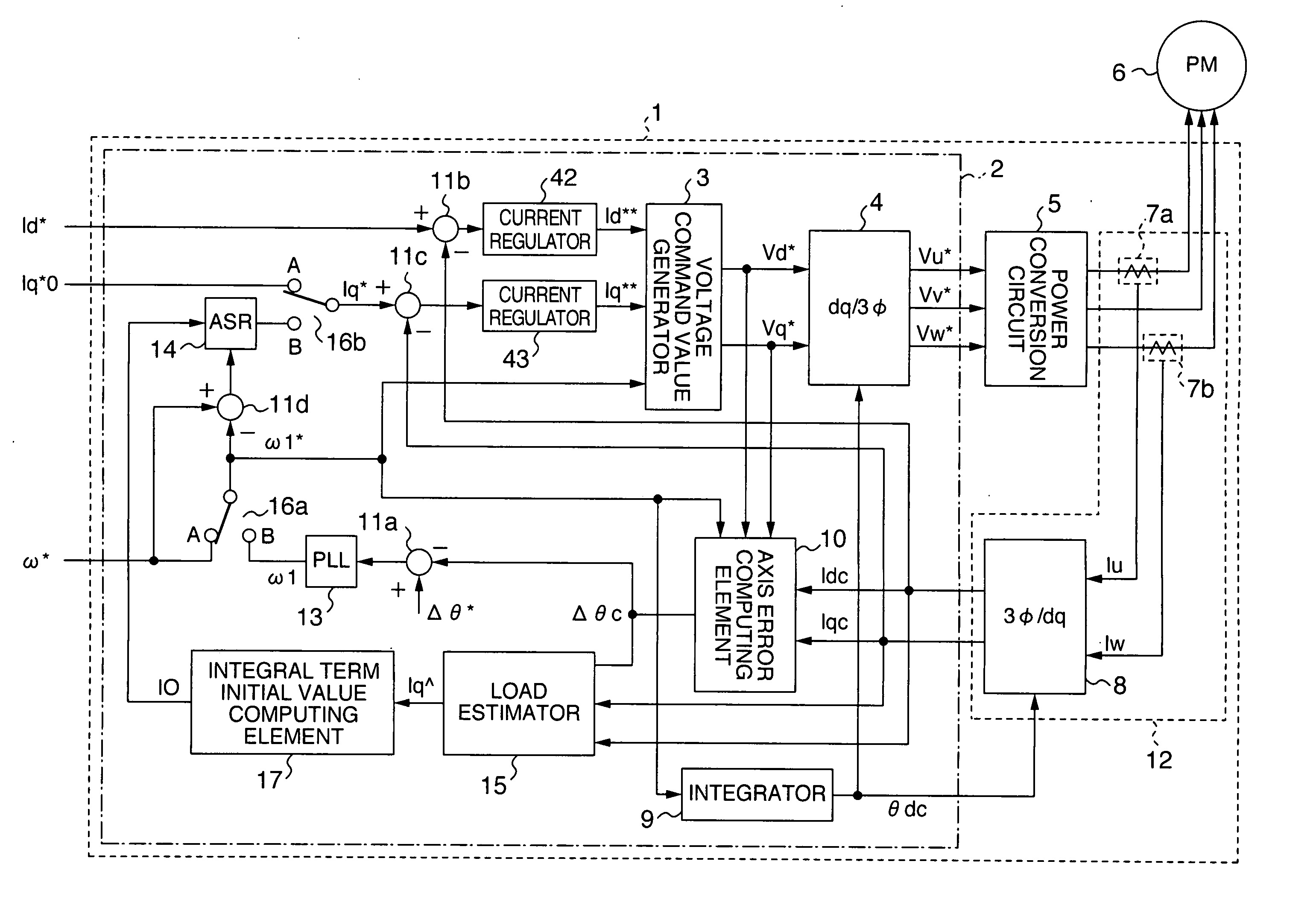
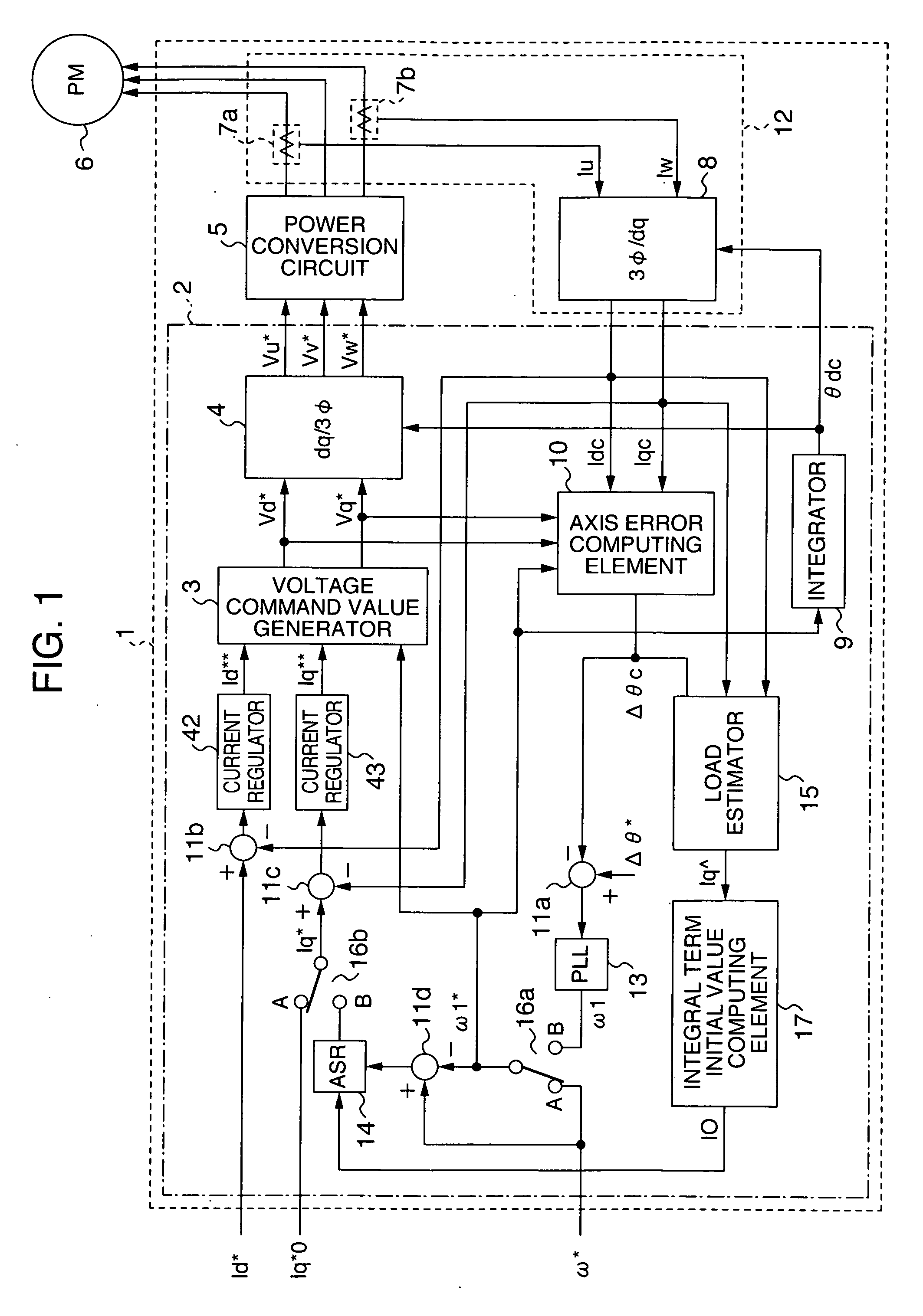
[0038]FIG. 1 is a basic configuration diagram of a motor controller according to the present invention. When broadly divided, a motor controller 1 includes a current detector 12, a control unit 2 for receiving a d-axis detected current Idc and a q-axis detected current Iqc output from the current detector 12, conducting arithmetic operation, and outputting three-phase voltage command values (Vu*, Vv*, Vw*) to be finally applied to a permanent magnet motor (PM) 6, and a power conversion circuit 5 for applying voltages according to the three-phase voltage command values (Vu*, Vv*, Vw*) to the permanent magnet motor 6.

[0039] The current detector 12 includes motor current detectors (7a and 7b) for detecting currents Iu and Iw respectively flowing through the U-phase and W-phase included in three-phase AC currents flowing through the motor, and a 3Ø / dq converter 8 for con...

second embodiment

[0075] A second embodiment of the motor controller 1 according to the present invention will now be described with reference to FIGS. 13 to 16. The second embodiment differs from the first embodiment in the configuration of the current detector for finding the d-axis detected current and the q-axis detected current flowing through the motor and the way of current command values in the synchronous operation mode.

[0076] As shown in FIG. 13, a current detector 12a includes a current detection circuit 7c, a motor current reconstruction computing element 41 for reproducing three-phase AC currents (Iu, Iv and Iw) from an inverter input DC current IDC detected by the current detection circuit 7c, and a 3θ / dq converter 8a for converting three-phase axes to the dq axes and finding the d-axis and q-axis detected currents (Idc and Iqc).

[0077] In the present embodiment, means for detecting the inverter input DC current IDC of a power conversion circuit 5a has a configuration using a current d...

third embodiment

[0093] Hereafter, a third embodiment of the motor controller according to the present invention will be described.

[0094]FIG. 17 is a general configuration diagram of a motor controller 1b in the present embodiment. The present embodiment differs from the two embodiments described earlier in the configuration of the load estimator. A load estimator 15a has a configuration supplied with the d-axis and q-axis voltage command values (Vd* and Vq*) and the d-axis and q-axis detected currents (Idc and Iqc) to conduct arithmetic operation to find the active power and the torque estimated value (τˆ) of the permanent magnet motor according to the following expression. τ⁢ ^=⁢(Wp-Wcu) / ω⁢ ⁢r=⁢{(3 / 2)×(Vd*×Idc+Vq*×Iqc)-⁢(3 / 2)×R×(Idc⁢ ^⁢2+Iqc⁢ ^⁢2)} / (ω* / P)(expression⁢ ⁢8)

[0095] In the (expression 8), Wp is the active power, Wcu is the copper loss, ωr is the actual rotational frequency of the permanent magnet motor, R is the primary winding resistance value of the permanent magnet motor 6, ω* is t...


PUM


Abstract

A motor controller capable of suppressing a large speed change generated at the time of changeover from a synchronous operation mode to a position feedback operation mode and implementing even acceleration characteristics regardless of the load torque by estimating a torque of a permanent magnet motor in the synchronous operation mode for driving the permanent magnet motor and setting an initial value of a current command value in a position sensor-less operation mode on the basis of information of the torque estimated value.

Description

BACKGROUND OF THE INVENTION [0001] The present invention relates to a motor controller for stably driving a permanent magnet motor. [0002] For starting a permanent magnet motor, the following method is known. The method includes the steps of: [0003] letting a current flow through a specific phase and positioning a rotor, as a positioning mode; [0004] then driving a synchronous motor without using information of a rotational angle position of the permanent magnet motor (without conducting position feedback), raising the output frequency of an inverter gradually, and accelerating the permanent magnet motor to a certain number of rotations from the positioning state, as a synchronous operation mode; and [0005] then conduct operation at that number of rotations or above by using an estimated value of a magnetic pole position or information of the rotational angle position obtained from a magnetic pole position sensor or the like, as a position feedback operation mode. [0006] When changi...

Claims


Application Information

Patent Timeline
IPC IPC(8): H02P3/18H02P6/06H02P6/08H02P6/18H02P6/182
CPCH02P6/20H02P21/0035H02P21/22
Inventor SUZUKI, TAKAHIROENDO, TSUNEHIROTOBARI, KAZUAKIKANEKO, DAIGOMAEDA, DAISUKEYAMAZAKI, AKIRA
Owner HITACHI POWER SEMICON DEVICE
Why Eureka
Try Eureka