Magnetic bridge electric power sensor

a technology of power sensor and magnetic bridge, which is applied in the direction of power measurement by galvanomagnetic effect devices, measurement devices, instruments, etc., can solve the problems of difficult integration of this power meter into a recently required automated apparatus, inability to simply calculate the power using ac power supply, and inability to measure direct-current power, etc., to achieve high sensitivity and high accuracy

Inactive Publication Date: 2007-02-01
LOYAL PORT
View PDF2 Cites 19 Cited by
  • Summary
  • Abstract
  • Description
  • Claims
  • Application Information

AI Technical Summary

Benefits of technology

[0012] The present invention has been achieved in view of the conventional disadvantages. It is an object of the present invention to provide a high sensitivity, ...

Problems solved by technology

However, a power using an alternating-current (AC) power supply cannot be simply calculated since the power includes an effective power that is consumed as an energy and an ineffective power that is not consumed as the energy.
With this conventional method, an AC power can be measured but a direct-current (DC) power cannot be measured because of characteristics of the CT and the VT.
Due to this, it is difficult to incorporate this power meter into a recently required automated apparatus and to use it sequentially with a digital signal processing.
Actually, the power meter cannot be used for these purposes.
Thi...

Method used


Image

  • Magnetic bridge electric power sensor
  • Magnetic bridge electric power sensor
  • Magnetic bridge electric power sensor

Examples


Embodiment Construction

[0074] Referring to FIG. 6, a power sensor in which inverting method is adapted to a modulation excitation current will be described.

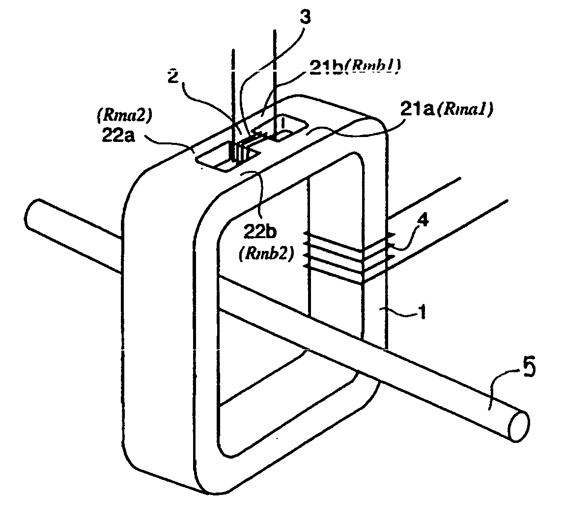
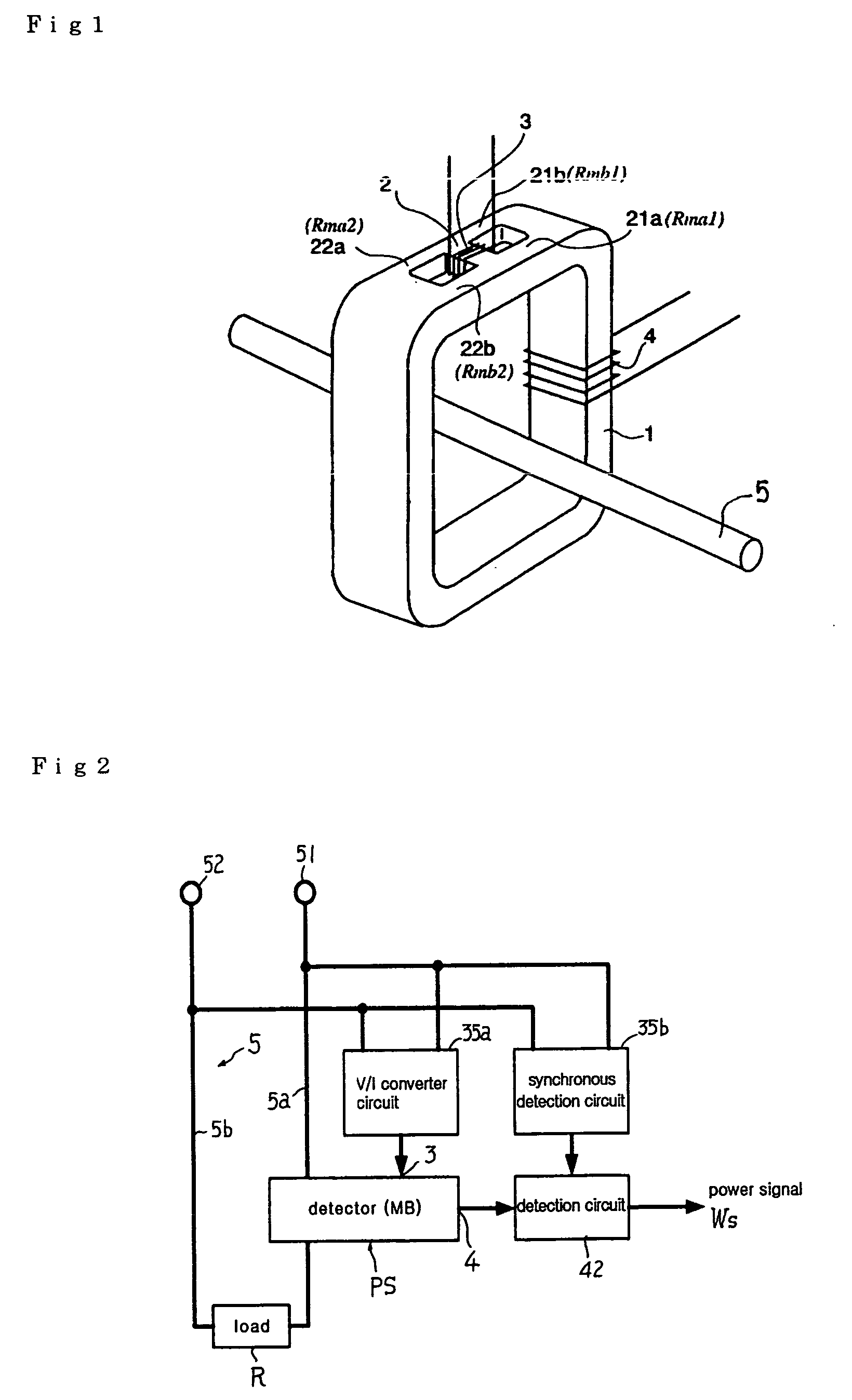
[0075] In FIG. 6, reference numeral5 denotes a measurement target power line. The power line 5 includes detection target current conductors 5a and 5b to which a detector PS using a magnetic bridge (MB) is attached, and load R is connected to power receiving terminals thereof. Reference numerals 51 and 52 denote power transmission terminals of the power line 5. Reference numeral 3 denotes an excitation coil provided in a core of the detector PS. A current obtained by inverting a current of the power line 5 using a switching unit 31 is carried to the excitation coil 3. The switching unit 31 includes semiconductor switches, e.g., photo switches SW1 and SW2 as shown in FIG. 6. Alternatively, switches other than the semiconductor switches can be used. A current-limiting resistor 31R which operates voltage-current conversion is interposed between the power ...


PUM


Abstract

A magnetic bridge power sensor including a magnetic bridge that includes: a magnetic circuit 1 having two ends; magnetic circuits 21a and 21b each having two ends, one of the two ends of each of the magnetic circuits 21a and 21b being connected to one of the two ends of the magnetic circuit 1; magnetic circuits 22b and 22a each having two ends, one of the two ends of each of the magnetic circuits 22b and 22a being connected to the other end of the magnetic circuit 1, the other ends of the magnetic circuits 22b and 22a being connected to the magnetic circuits 21a and 21b, respectively; a magnetic circuit 2 having two ends, the two ends being connected to a connection point between the magnetic circuit 21a and the magnetic circuit 22b and to a connection point between the magnetic circuit 21b and the magnetic circuit 22a, respectively; an excitation coil 3 provided to be able to generate a magnetic flux in the magnetic circuit 2; and a magnetic flux detection coil 4 provided to be able to detect the magnetic flux in the magnetic circuit 1. A current, which is obtained by subjecting a current proportional to a voltage on a measurement target power line 5 to at least one of an intermittent processing and an inverting processing, is carried to the excitation coil 3. The current of the measurement target power line 5 is carried to a detection target current conductor 5a. An output of the detection coil 4 is synchronously detected by a signal having a phase synchronized with a cycle of the intermittent processing or the inverting processing at a frequency twice as high as a frequency of the intermittent processing or the inverting processing.

Description

TECHNICAL FIELD [0001] The present invention relates to a power sensor for measuring a power by simultaneously detecting a current and a voltage by one sensor and physically multiplying the current by the voltage by the sensor itself. BACKGROUND ART [0002] A power can be calculated from a voltage on both ends of a load and a current carried to the load. Specifically, the power can be obtained by multiplying a load current carried to the load by a load voltage applied to the load. However, a power using an alternating-current (AC) power supply cannot be simply calculated since the power includes an effective power that is consumed as an energy and an ineffective power that is not consumed as the energy. [0003] Conventionally, there is generally known the following method for detecting a power. A current detection transformer (CT) calculates the load current, and a voltage detection transformer (VT) calculates the load voltage. In addition, an electronic circuit or a microcomputer mul...

Claims


Application Information

Patent Timeline
IPC IPC(8): G01R15/18G01R21/06G01R21/08
CPCG01R21/06G01R15/183G01R21/08
Inventor TADATSU, TAKASHI
Owner LOYAL PORT
Why Eureka
Try Eureka