Image forming method and charged particle beam apparatus
a technology of charged particle beam and image forming method, which is applied in the direction of pulse technique, television system, instruments, etc., can solve the problem of remaining inclined charging
- Summary
- Abstract
- Description
- Claims
- Application Information
AI Technical Summary
Benefits of technology
Problems solved by technology
Method used
Image
Examples
first embodiment
(First Embodiment)
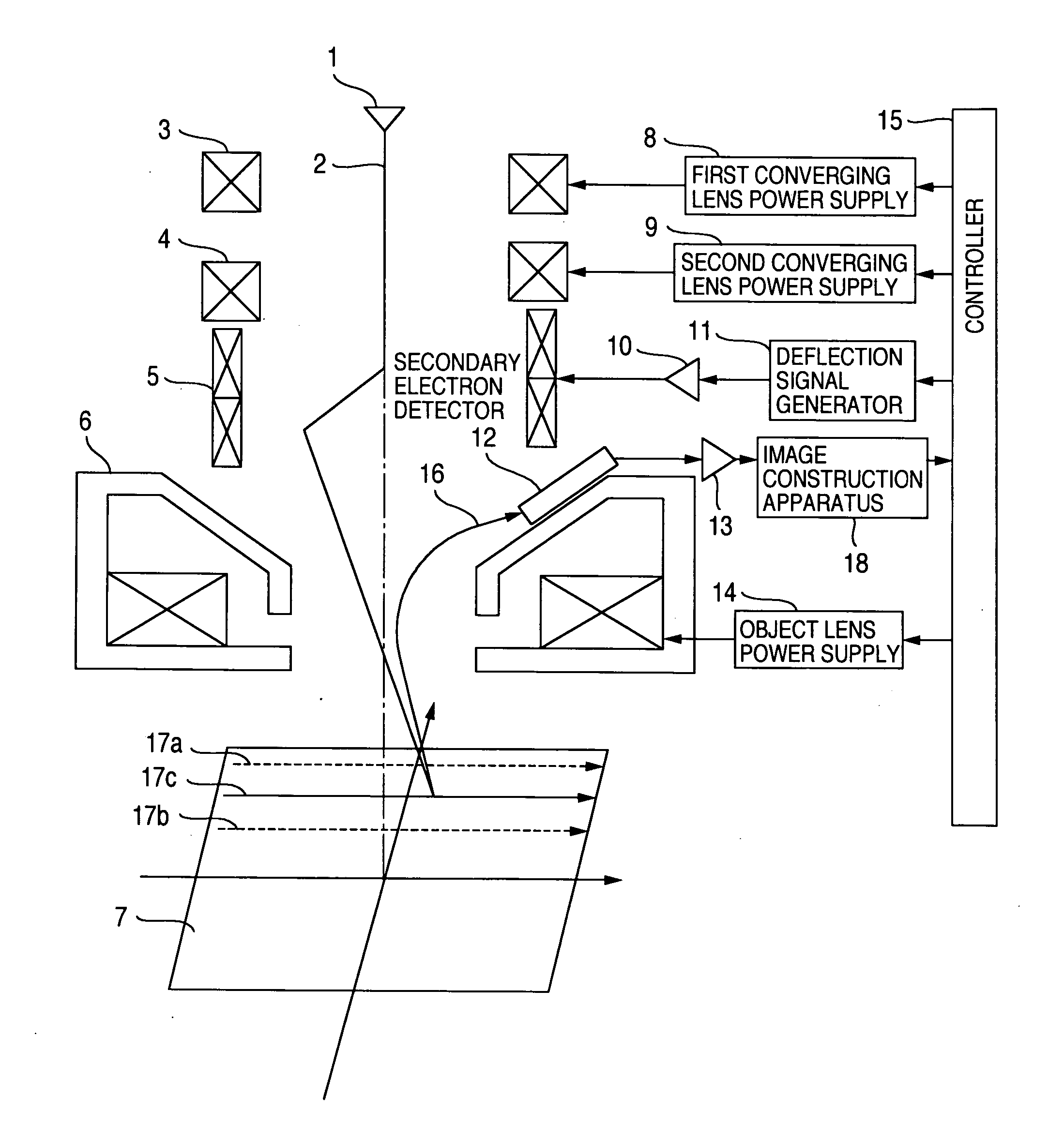
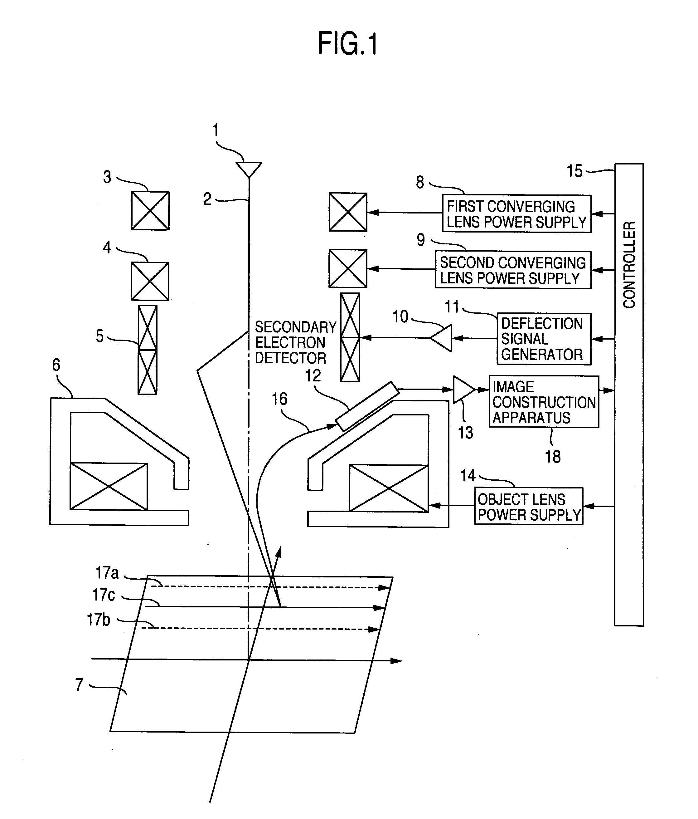
[0040] Hereafter, a first embodiment of the present invention will be described with reference to the drawings. A first embodiment of the present invention is shown in FIG. 1. The present embodiment will now be described by taking a scanning electron microscope which conducts scanning with an electron beam and forms a two-dimensional image of the sample as an example. However, the present embodiment is not restricted to this. If the influence of charging cannot be neglected, it is also possible to apply the present embodiment to an FIB (Focused Ion Beam) apparatus, which conducts scanning with an ion beam and forms an SIM (Scanning Ion Microscope) image.
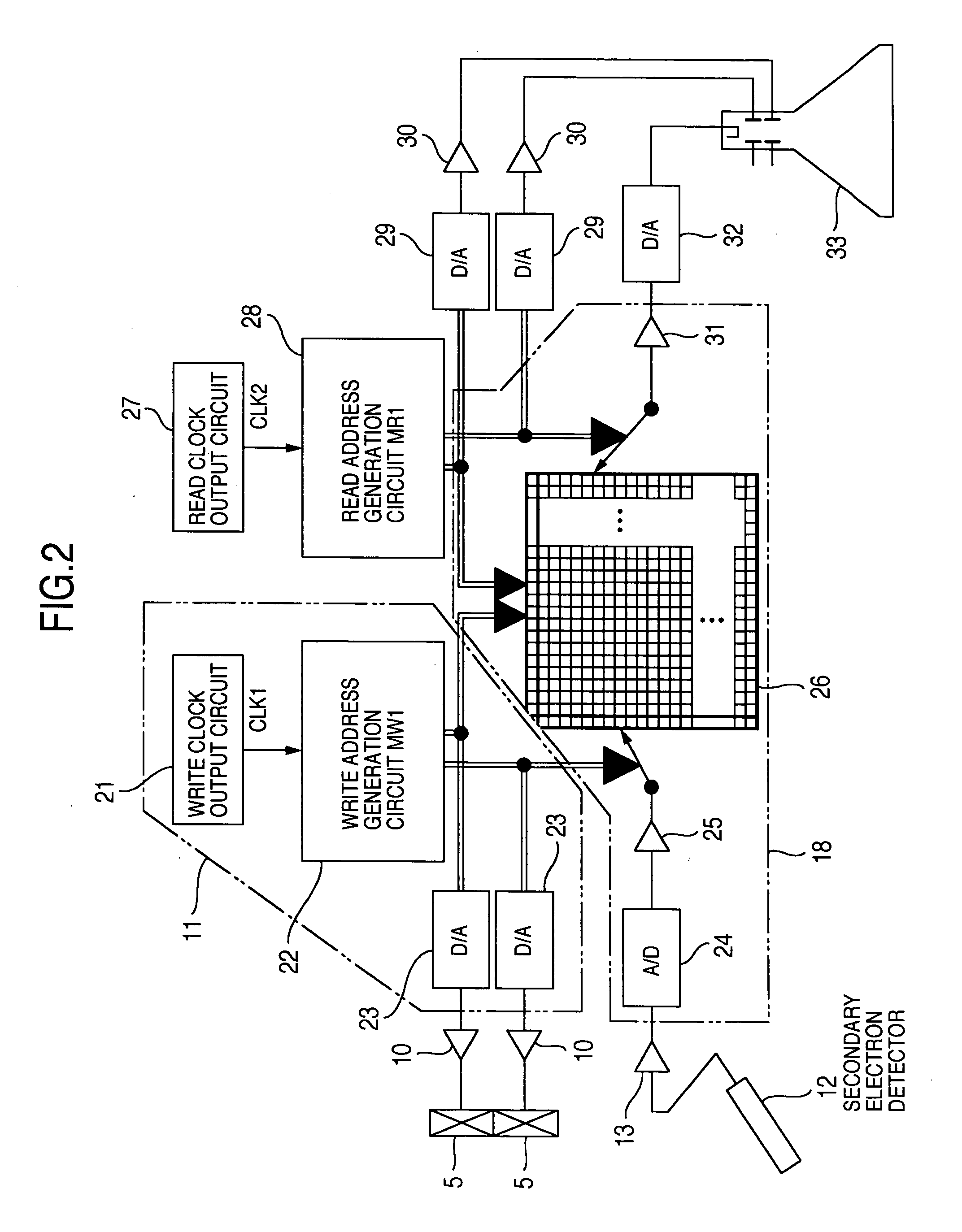
[0041] As shown in FIG. 1, the present embodiment includes an electron beam source 1, a first converging lens 3 and a second converging lens 4 for focusing a primary electron beam 2 emitted from the electron beam source 1, deflectors 5 for deflecting the primary electron beam 2 to scan a surface of a sample 7 with ...
second embodiment
(Second Embodiment)
[0069] An example in which pattern length measurement is conducted on the basis of an image formed using a scanning method of scanning a center line between scanning lines one after another as described above will now be described. FIG. 15 is a diagram showing an example of an image formed using the scanning method of the present example.
[0070] On this image, a line pattern bent in a part thereof by 90 degrees is displayed. When measuring the line width of such a line pattern, the scanning line direction of the raster scan and the sample direction are set in the conventional technique so as to make the pattern edge perpendicular to the scanning line direction of the raster scan. Because a length value measured in the scanning line direction of the raster scan becomes different from that measured in other directions as illustrated in FIG. 16 although the line width is the same. Since in this way the length value measured in the scanning line direction becomes diff...
third embodiment
(Third Embodiment)
[0077] An example of further mitigating the influence of the charging by combining a faster scanning rate with the scanning method described with reference to the first embodiment will now be described. FIGS. 17A and 17B are diagrams showing deflection patterns (deflection patterns E and F represented by solid lines) used when scanning using the electron beam is conducted at a scanning rate that is twice with respect to the deflection patterns A and B described in the first embodiment. Observation and measurement become possible even for a sample affected by the charging more remarkably by combining the suppression of charging obtained using scanning faster than the ordinary scanning with the scanning method described with reference to the first embodiment.
[0078]FIG. 22 is a diagram showing an example of a GUI (Graphical User Interface) for setting various scanning methods including the scanning method of the present example and the scanning rate. In a GUI screen ...
PUM
 Abstract
Description
Claims
Application Information
 - R&D
- Intellectual Property
- Life Sciences
- Materials
- Tech Scout
- Unparalleled Data Quality
- Higher Quality Content
- 60% Fewer Hallucinations
Browse by: Latest US Patents, China's latest patents, Technical Efficacy Thesaurus, Application Domain, Technology Topic, Popular Technical Reports.
© 2025 PatSnap. All rights reserved.Legal|Privacy policy|Modern Slavery Act Transparency Statement|Sitemap|About US| Contact US: help@patsnap.com


